 Honda Accord: Immobilizer-Keyless Control Unit
Replacement
Honda Accord: Immobilizer-Keyless Control Unit
Replacement
1 . Remove the driver's dashboard lower cover (see page 20-166).
2. Remove the steering column covers (see page 20-181).
3. Disconnect the 7P connector (A) from the immobilizer-keyless control unit (B).
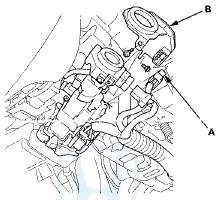
4. Remove the two screws and the immobilizer-keyless control unit.
5. Install the immobilizer-keyless control unit in the reverse order of removal.
6. After replacement register the immobilizer-keyless control unit (see page 22-439), and make sure the immobilizer system works properly.
7. Program all of the customer's keys/keyless transmitters (see page 22-439).
SUPPLEMENTAL RESTRAINT SYSTEM (SRS) (If Audio, Navigation, and Telematics maintenance required)
The Accord SRS includes a driver's airbag in t h e steering wheel hub, a passenger's airbag in the dashboard above the glove box, seat belt tensioners in the front seat belt retractors, side curtain airbags in the sides of the roof, and side airbags in the front seat-backs. Information necessary to safely service the SRS is included in this Service Manual. Items marked with an asterisk (*) on the contents page include or are located near SRS components. Servicing, disassembling, or replacing these items requires special precautions and tools, and should be done by an authorized Honda dealer.
• To avoid rendering the SRS inoperative, which could lead to personal injury or death in the event of a severe frontal or side collision, all SRS service work should be done by an authorized Honda dealer.
•Improper service procedures, including incorrect removal and installation of the SRS, could lead to personal injury caused by unintentional deployment of the airbags, side airbags, and/or side curtain airbags.
• Do not bump or impact the SRS unit, front impact sensors, side impact sensors, or rear safing sensor, especially when the ignition switch is in ON (II), or for at least 3 minutes after the ignitlon switch is turned to LOCK (0); o t h e r w i s e , the system may fail in a collision, or the airbags may deploy.
•SRS electrical connectors are identified by yellow color coding. Related components are located in the steering column, center console, dashboard, dashboard lower cover, in the dashboard above the glove box, in the front seats, in the roof side, and around the floor. Do not use electrical test equipment on these circuits.
 Immobilizer Key Registration
NOTE:
• The HDS is required for registration of the immobilizer
keys.
• Programming the immobilizer also programs the
keyless transmitter.
• Check for aftermarket electrical eq ...
 Audio, Navigation, and Telematics
Special Tools
...
See also:
Immobilizer Key Registration
NOTE:
• The HDS is required for registration of the immobilizer
keys.
• Programming the immobilizer also programs the
keyless transmitter.
• Check for aftermarket electrical eq ...
Paint Code
...
MICU Input Test
NOTE:
• Before testing, troubleshoot the multiplex
integrated control unit first, using B-CAN System Diagnosis Test Mode A
{see page 22-134).
• Before testing, make sure the No. 15 (7 ...