 Honda Accord: Self-diagnostic Function
NOTE: Before testing, troubleshoot the multiplex integrated control unit first, using B-CAN System Diagnosis Test Mode A (see page 22-134).
The gauge control module has a self-diagnostic function which consists of the following checks: • The beeper drive circuit check.
• The indicator drive circuit check.
• The switch input test.
• The LCD segments check.
• The gauges drive circuit check (Tachometer, Fuel gauge, Speedometer, Engine coolant temperature gauge.
• The communication line check (of the body-controller area network (B-CAN) communication line and the fast-controller area network (F-CAN) communication line between the gauges).
NOTE: Indicators are also controlled via the communication lines.
Entering the self-diagnostic function with the HDS
Using the HDS, select Body Electrical, Gauges, then Function Test and do the self-diagnostic function.
Entering the colf diagnostic function (manual method)
Before doing the self-diagnostic function, make sure the No. 5 (7.5 A) fuse in the driver's under-dash fuse/relay box and the No. 15 (10 A) fuse in the under-hood fuse/relay box are OK.
1. Push and hold the SEL/RESET button.
2. Turn the combination light switch
 ON.
ON.
3. Turn the ignition switch to ON (II).
4. Within 5 s e c , turn the combination light switch
 OFF, then ON and OFF again.
5. Within 5 s e c , release the SEL/RESET button, and then push and release the burton three times repeatedly.
NOTE: • While in the self-diagnostic mode, the dashlights brightness controller operates normally.
• While in the self-diagnostic mode, the SEL/RESET switch is used to start the Beeper Drive Circuit Test and the Gauge Drive Circuit Check.
• If the vehicle speed exceeds 1.2 mph (2 km/h) or the ignition switch is turned to LOCK (0), the self-diagnostic mode ends.
The Indicator Drive Circuit Check
When entering the self-diagnostic mode, the following indicators (if equipped) blink: A/T gear position indicator, ABS indicator, brake system indicator, charging system indicator, cruise control indicator, cruise main indicator, door indicator, DRL indicator, high beam indicator, immobilizer indicator, lights-on indicator, low oil pressure indicator, low fuel indicator, low tire pressure indicator, malfunction indicator lamp (MIL), maintenance required indicator, seat belt indicator, security indicator, side airbag cutoff indicator, SRS indicator, TPMS indicator, trunk indicator, VSA activation indicator, VSA indicator, and washer fluid level indicator (Canada models).
Switch Input Check
At the initial stage of the self-diagnostic function, the beeper sounds intermittently. The beeper sounds continuously when any of the following switch inputs are switched from OFF to ON: Cruise control main, SET/DECEL, RESUME/ACCEL, CANCEL switches, SEL/RESET switch, parking brake switch, and VSA OFF switch.
The Beeper Drive Circuit Check
When entering the self-diagnostic mode, the beeper sounds five times.
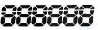
The LCD Segment Check
When entering the self-diagnostic mode, all the segments blink five times.
The Gauge Drive Circuit Check
When entering the self-diagnostic mode, the speedometer, the tachometer, the fuel gauge, and the engine coolant temperature gauge needles sweep from the minimum position to maximum position, then return to the minimum position.
NOTE: After the beeper stops sounding and the gauge needles return to the minimum position, pushing the SEL/RESET button starts the Beeper Drive Circuit Check (one beep) and the Gauge Drive Circuit Check again.
The check cannot be started again until the gauge needles return to the minimum position.
If the needles fail to sweep, or the beeper does not sound, replace the gauge control module.
The Communication Line Check
While in the self-diagnostic mode, the Communication Line Check starts after the LCD Segments Check.
If all segments come on, the communication line is OK. If faulty, the word Error will be indicated on the odometer display followed by a number(s).
Error Code List
Example Indication
Normal (all segments come on.):
Faulty (Error 1):

• If Error 1 is indicated, there is a malfunction in the communication line between the F-CAN and the gauge control module. The B-CAN is OK at this time. Check for DTCs in the F-CAN connected units and troubleshoot any DTCs found.
If no DTCs are found, go to B-CAN System Diagnosis Test Mode A (see page 22-134).
• If Error 2 is indicated, there is a malfunction in the communication line between the B-CAN and the gauge control module. The F-CAN line is OK at this time. Go to B-CAN System Diagnosis Test Mode A (see page 22-134).
• If Error 12 is indicated, there is a malfunction in the communication line between the gauge control module, the F-CAN, and the B-CAN. Check the DTCs in the F-CAN connected units and troubleshoot any DTCs found. If no DTCs are found, go to B-CAN System Diagnosis Test Mode A (see page 22-134).
Ending the self-diagnostic function
Turn the ignition switch to LOCK (0).
NOTE: If the vehicle speed exceeds 1.2 mph (2 km/h), the self-diagnostic function ends.

 Circuit Diagram
...
See also:
Back-up Light Switch Test
1. Disconnect the back-up light switch 2P connector (A).
2. Check for continuity between back-up light switch 2P
connector terminals No. 1 and No. 2. There should be
continuity only when the shif ...
Front Passenger's Power Window
Motor Test
With AUTO UP/AUTO DOWN function
Motor Test
1. Remove the front passenger's power window switch:
• 4-door (see page 22-306)
• 2-door (see page 22-307)
2. Test the motor in each direction ...
Passenger's Dashboard Trim
Removal/Installation
Special Tools Required
KTC Trim Tool Set SOJATP2014*
* Available through the Honda Tool and
Equipment
Program; call 888-424-6857
NOTE:
- Take care not to scratch the dashboard or the related
p ...