 Honda Accord: General Troubleshooting Information
How to Check for DTCs with the Honda Diagnostic S f stem (HDS)
When the powertrain control module (PCM) senses an abnormality in the input or output system, the D indicator (A) in the gauge control module ( i ) will usually blink.
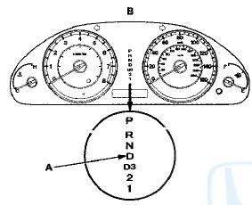
When the Honda Diagnostic System (HDS) is connected to the data link connector (DLC) (A) located under the driver's side of the dashboard, it wilt indicate the diagnostic trouble code (DTC) when the ignition switch is turned to ON (11) and the appropriate menu is selected.
If the D indicator or the malfunction indicator lamp (MIL) has been reported on, or if a driveability problem is suspected, follow this procedure: 1. Connect the HDS to the DLC. (See the HDS user's manual for specific instructions.) 2. Turn the ignition switch to ON (II). Make sure the HDS communicates with the PCM. If it does not, go to the DLC circuit troubleshooting (see page 11-181).
3. Check for Pending or Confirmed DTCs with the HDS.
4. Record the freeze data and the on-board snapshots for all fuel and emissions DTCs and A/T DTCs.
5. If there is a fuel and emissions DTC, first check the fuel and emissions system as indicated by the DTC, 6. Clear the DTC and the data.
7. Drive the vehicle for several minutes under the same conditions as those indicated by the freeze data, and then recheck for a DTC. If the A/T DTC returns, go to the indicated DTCs troubleshooting. If the DTC does not return, there was an intermittent problem within the circuit. Make sure all pins and terminals in the circuit are tight.
Symptom Troubleshooting Versus DTC Troubleshooting
Some symptoms will not set DTCs or cause the D indicator to blink. If the MIL was reported ON or the D indicator has been blinking, check for DTCs. If the vehicle has an abnormal symptom, and there are no DTCs stored, do the symptom troubleshooting. Check the list of probable cause(s) for the symptom, in the sequence listed, until you find the problem.
How to Check for DTCs with the SCS Mode (retrieving the flash codes)
NOTE: The preferred method Is to use the HDS to retrieve the DTCs.
When the PCM senses an abnormality in the input or output system, the D indicator (A) in the gauge control module (B) will usually blink.
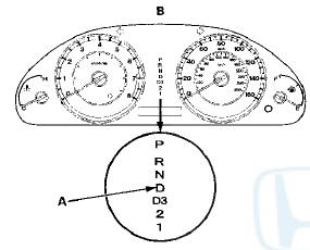
When the D indicator has been reported on, connect the HDS to the DLC (A) located under the driver's side of the dashboard. Turn the ignition switch to ON (II), select SCS mode, then the D indicator will indicate (blink) the DTC.
If the D indicator and the MIL come on at the same time, or if a drivability problem is suspected, follow this procedure: 1. Connect the HDS to the DLC. (See the HDS user's manual for specific instructions.) 2. Turn the ignition switch to ON (II). Make sure the HDS communicates with the PCM. If it does not, go to the DLC circuit troubleshooting (see page 11-181).
3. Select SCS mode, then observe the D indicator in the gauge control module. Codes 1 through 9 are indicated by individual short blinks. Code 10 and above are indicated by a series of long and short blinks. One long blink equals 10 short blinks. Add the long and short blinks together to determine the code.
Example: DTC P0705 (5)
Example: DTCP0717(15)
4. Record all fuel and emissions DTCs and A/T DTCs.
5. If there is a fuel and emissions DTC, first check the fuel and emissions system as indicated by the DTC.
6. Clear the DTC and the data.
7. Drive the vehicle for several minutes under the same conditions as those indicated by the freeze data, and then recheck for DTCs. If the A/T DTC returns, go to the indicated DTCs troubleshooting. If the DTC does not return, there was an intermittent problem within the circuit. Make sure all pins and terminals in the circuit are tight.
How to Troubleshoot Circuits at the PCM Connectors
NOTE: The PCM overwrites data and monitors the EVAP system for about 40 minutes after the ignition switch is turned to LOCK (0). Jumping the SCS line after turning the ignition switch to LOCK (0) cancels this function.
Disconnecting the PCM during this function, without jumping the SCS line first, can damage the PCM.
1. Jump the SCS line with the HDS.
2. Remove the bolts (D).
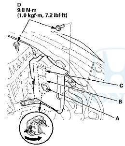
3. Disconnect PCM connectors A, B, and C.
NOTE: PCM connectors A, B, and C have symbols
(A= , B=
, B= ,
,
C= ) embossed on them for
identification.
4. When diagnosis/troubleshooting is done at the PCM connector, use the terminal test port (A) above the terminal you need to check.
5. Connect one side of the patch cord terminals (A) to a commercially available digital multimeter (B), and connect the other side of the patch cord terminals (C) to a commercially available banana jack (Pomona Electronics Tool No. 3563 or equivalent) (D).
6. Gently insert the pin probe (male) into the terminal test port from the terminal side. Do not force the tips into the terminals.

-For accurate results, always use the pin probe (male).
-To prevent damage to the connector terminals, do not insert test equipment probes, paper clips, or other substitutes as they can damage the terminals.
Damaged terminals cause a poor connection and an incorrect measurement.
-Do not puncture the insulation on a wire. Punctures can cause poor or intermittent electrical connections.
Clear A/T DTCs Procedure
1. Connect the HDS to the DLC (A) located under the driver's side of the dashboard.
2. Turn the ignition switch to ON (II).
3. Make sure the HDS communicates with the PCM. If it does not, go to the DLC circuit troubleshooting (see page 11-181).
4. Clear the DTC(s) with the HDS.
OBD Status
The OBD status shows the current system status of each DTC and all of the parameters. This function is used to see if a repair was successfully completed. The results of diagnostic tests for the DTC are displayed as: -PASSED: The on-board diagnosis is successfully completed.
-FAILED: The on-board diagnosis is finished but failed.
-NOT COMPLETED: The on-board diagnosis was running but is out of the enable conditions of the DTC.
How to End a Troubleshooting Session (required after any troubleshooting)
NOTE: Reset the PCM/TCM with the HDS while the engine is stopped.
1. Turn the ignition switch to LOCK (0).
2. Turn the ignition switch to ON (II), and wait for 30 seconds.
3. Turn the ignition switch to LOCK (0), and disconnect the HDS from the DLC.
4. Start the engine with the shift lever in P or N, and warm it up to normal operating temperature (the radiator fan comes on).
5. To verify that the problem is repaired, test-drive the vehicle for several minutes at speeds over 31 mph (50 km/h) or under the same conditions as those indicated by the freeze data.
PCM/TCM Reset
NOTE: To reset the PCM/TCM, initialize only the automatic transmission memory stored in the PCM or the TCM.
1. Select the A/T system with the HDS.
2. Reset the PCM/TCM with the HDS while the engine is stopped.
3. Turn the ignition switch to LOCK (0).
4. Turn the ignition switch to ON (II), and wait for 30 seconds.
5. Turn the ignition switch to LOCK (0), and disconnect the HDS from the DLC.
Failure Reproduction Technique
Make sure to follow these points while the vehicle is raised on a lift for the test-drive.
-Disable the VSA by pressing the VSA OFF button.
-ABS or VSA DTC(s) may come on when test-driving on a lift. If the ABS or VSA DTC(s) come on, clear the DTC (s) with the HDS.
 Special Tools
: Must be used with commercially
available 3/8"-16 slide hammer.
...
 DTC Troubleshooting Index
NOTE: Before you troubleshoot record all freeze data and any on-board
snapshot with the HDS, and review General
Troubleshooting Information (see page 14-4).
NOTE:
*1: The DTC in parentheses is ...
See also:
Trunk Lid Latch Replacement
Special Tools Required
KTC Trim Too! Set SOJATP2014*
*Available through the Honda Tool and
Equipment
Program; call 888-424-6857
NOTE:
- Put on gloves to protect your hands.
- Take care not t ...
PCV Valve Inspection
1. Check the PCV valve (A), hoses (B), and connections
for leaks or restrictions.
1.PCV valve when the hose between the PCV valve and
intake manifold is lightly pinched (A) with your fingers
or ...
Component Location Index
'10 model
With navigation
Without navigation
...