 Honda Accord: 4th and 5th Clutch Reassembly
Special Tools Required
Clutch Spring Compressor Set 07LAE PX40000 1. Soak the clutch discs thoroughly in ATF for at least 30 minutes.
2. Install new O-rings (A) on the clutch piston (B). Do not twist the O-rings.
3. Install the clutch piston (A) in the clutch drum (B) while applying pressure and rotating to ensure proper seating. Do not pinch the O-ring.
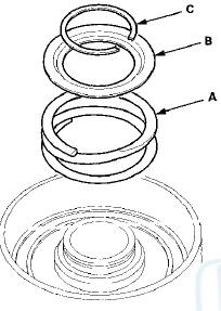
4. Set the return spring (A) and the spring retainer (B) on the clutch piston, and position the snap ring (C) on the spring retainer.
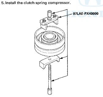
6. Be sure the clutch spring compressor (A) is adjusted to make f u l l contact with the spring retainer (B).
7. Check the placement of the clutch spring compressor, If either end of the clutch spring compressor is set over an area of the spring retainer that is unsupported by the return spring, the retainer may be damaged.
8. Compress the return spring until the snap ring can be installed.
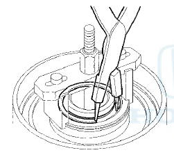
9. Install the snap ring using snap ring pliers.
10. Remove the clutch spring compressor.
11. Install the wave spring (A) in the 4th clutch drum (B).
Starting with the clutch wave-plate, alternately install the wave-plates (C) (4) and the clutch discs (D) (4).
Install the clutch end-plate (E) with the flat side toward the top disc.
12. Install the wave spring (A) in the 5th clutch drum (B).
Starting with the clutch wave-plate, alternately install the wave-plates (C) (4) and the clutch discs (D) (4).
Install the clutch end-plate (E) with the flat side toward the top disc.
13. Install the snap ring using a screwdriver to secure the clutch end-plate.
14. Check that the clutch piston moves by applying air pressure into fluid passage.
 1st, 2nd, and 3rd Clutch Reassembly
Special Tools Required
Clutch Spring Compressor Set 07LAE-PX40000
NOTE: Hold the spring compressor in a vise with soft
jaws. Be careful not to damage the clutch drum.
1 Soak the clutch discs tho ...
 Valve Body
Valve Body and ATF Strainer
Installation
Exploded View
Torque Specifications:
6 x 1.0 mm: 12 N-m (1.2 kgf m, 8.7 Ibfft)
8 x 1.25 mm: 18 N-m (1.8 kgfm, 13 Ibfft)
NOTE: Refer to the Exploded Vie ...
See also:
Locking/Unlocking the Doors from the Inside
• Using the Lock Tab
• Locking a door
Push the lock tab forward.
• Unlocking a door
Pull the lock tab rearward.
When you lock the door using the lock tab on the
driver's door, all the o ...
Steering Column Removal and Installation
SRS components are located in this area. Review the
SRS component locations: 4-door (see page 24-21 )f
2-door (see page 24-23) and the precautions and
procedures (see page 24-25) before doing repai ...
Starting the Engine
1. Make sure the parking brake is applied.
2. Check that the shift lever is in
, then
depress the brake pedal.
- Although it is possible to start the vehicle
in , it is safer to st ...