 Honda Accord: DTC Troubleshooting
DTC indicator 1:
An Open in the Air Mix Control Motor Circuit
1. Turn the ignition switch to LOCK (0), and then to ON (II).
2. Do the self-diagnostic function with the HVAC control unit (see page 21-9).
3. Check for DTCs.
Is DTC 1 indicated? YES
-Go to step 4.
NO
-lntermittent failure. Check for loose wires or poor connections on the air mix control motor circuit.
4. Turn the ignition switch to LOCK (0).
5. Test the air mix control motor (see page 21-59).
Is the air mix control motor OK? YES
-Go to step 6.
NO
-Replace the air mix control motor (see page 21-60).
6. Disconnect the air mix control motor 7P connector.
7. Disconnect the HVAC control unit 24P connector.
8. Check for continuity between the following terminals of the HVAC control unit 24P connector and the air mix control motor 7P connector.
24P: 7P:
No. 13 No. 5
No. 15 No. 7
No. 17 No. 3
HVAC CONTROL UNIT 24P CONNECTOR
Wire side of female terminals
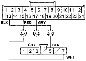
AIR MIX CONTROL MOTOR 7P CONNECTOR
Wire side of female terminals
Is there continuity? YES
-Check for loose wires or poor connections at the HVAC control unit 24P connector, and at the air mix control motor 7P connector. If the connections are good, substitute a known-good HVAC control unit and recheck. If the symptom/indication goes away, replace the original HVAC control unit (see page 21-65).
NO
-Repair an open in the wire(s) between the HVAC control unit and the air mix control motor.
DTC indicator 2;
A Short In the Air Mix Control Motor Circuit
1. Turn the ignition switch to LOCK (0), and then to ON (II).
2. Do the self-diagnostic function with the HVAC control unit (see page 21-9).
3. Check for DTCs.
Is DTC 2 indicated? Y E S
- G o to step 4.
NO
-lntermittent failure. Check for loose wires or poor connections on the air mix control motor circuit.
4. Turn the ignition switch to LOCK (0).
5. Test the air mix control motor (see page 21-59).
Is the air mix control motor OK? Y E S
- G o to step 6.
NO
-Replace the air mix control motor (see page 21-60).
6. Disconnect the air mix control motor 7P connector.
7. Disconnect the HVAC control unit 24P connector.
8. Check for continuity between body ground and HVAC control unit 24P connector terminals No. 13 and No.
17 individually.
HVAC CONTROL UNIT 24P CONNECTOR
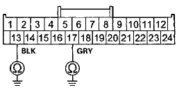
Wire side of female terminals
Is there continuity? Y E S
- R e p a i r a short to body ground in the wire(s) between the HVAC control unit and the air mix control motor.
NO
-Go to step 9.
9. Check for continuity between HVAC control unit 24P connector terminals No. 13 and No. 17.
HVAC CONTROL UNIT 24P CONNECTOR
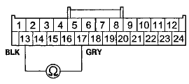
Wire side of female terminals
Is there continuity? Y E S
- R e p a i r a short in the wires.
NO
-Go to step 10.
10. Turn the ignition switch to ON (ll), and check the same terminals for voltage between each terminal and body ground.
HVAC CONTROL UNIT 24P CONNECTOR
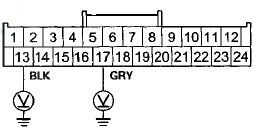
Wire side of female terminals
Is there any voltage? Y E S
- R e p a i r a short to power in the wire(s) between the HVAC control unit and the air mix control motor.
This short may also damage HVAC control unit.
Repair a short to power before replacing the HVAC control unit.
NO
-Substitute a known-good HVAC control unit and recheck. If the symptom/indication goes away, and the air mix control motor runs, replace the original HVAC control unit (see page 21-65)
DTC Indicator 3:
A Problem in the Air Mix Control Linkage, Door, or Motor Circuit
1. Turn the ignition switch to LOCK (0), and then to ON (II).
2. Do the self-diagnostic function with the HVAC control unit (see page 21-9).
3. Check for DTCs.
Is DTC 3 indicated? YES
-Go to step 4.
NO
-lntermittent failure. Check for loose wires or poor connections on the air mix control motor circuit.
4. Turn the ignition switch to LOCK (0).
5. Test the air mix control motor (see page 21-59).
Is the air mix control motor OK? YES
-Go to step 6.
NO
-Replace the air mix control motor (see page 21-60), or repair the air mix control linkage or door.
6. Disconnect the air mix control motor 7P connector.
7. Disconnect the HVAC control unit 24P connector.
8. Check for continuity between the following terminals of the HVAC control unit 24P connector and the air mix control motor 7P connector.
24P: 7P:
No. 5 No. 1
No. 6 No. 2
HVAC CONTROL UNIT 24P CONNECTOR
Wire side of female terminals
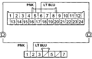
AIR MIX CONTROL MOTOR 7P CONNECTOR
Wire side of female terminals
Is there continuity? YES
-Go to step 9.
NO
-Repair an open in the wire(s) between the HVAC control unit and the air mix control motor.
9. Check for continuity between body ground and HVAC control unit 24P connector terminals No. 5 and No. 6 individually.
HVAC CONTROL UNIT 24P CONNECTOR
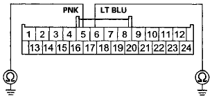
Wire side of female terminals
Is there continuity? YES
-Repair a short to body ground in the wire(s) between the HVAC control u n i t and the air mix control motor.
NO-
Substitute a known-good HVAC control unit, and recheck. If the symptom/indication goes away, replace the original HVAC control unit (see page 21-65).
DTC indicator 4:
An Open in the Mode Control Motor Circuit
'08-10 models with M/T and '08-09 models 2-door with A/T
1. Turn the ignition switch to LOCK (0), and then to ON (II).
2. Do the self-diagnostic function with the HVAC control unit (see page 21-9).
3. Check for DTCs.
Is DTC 4 indicated? YES
-Go to step 4.
NO
-lntermittent failure. Check for loose wires or poor connections on the mode control motor circuit.
4. Turn the ignition switch to LOCK (0).
5. Test the mode control motor (see page 21-61).
is the mode control motor OK? YES
-Go to step 6.
NO
-Replace the mode control motor (see page 21-62).
6. Disconnect the mode control motor 7P connector.
7 Disconnect the HVAC control unit 24P connector.
8. Check for continuity between the following terminals of the HVAC control unit 24P connector and the mode control motor IP connector.
24P: 7P:
No. 13 No. 5
No. 15 No. 7
No. 16 No. 3
HVAC CONTROL UNIT 24P CONNECTOR
Wire side of female terminals

MODE CONTROL MOTOR 7P CONNECTOR
Wire side of female terminals
Is there continuity? YES
-Check for loose wires or poor connections at the HVAC control unit 24P connector, and at the mode control motor 7P connector. If the connections are good, substitute a known-good HVAC control unit and recheck. If the symptom/indication goes away, replace the original HVAC control unit (see page 21-65).
NO
-Repair an open in the wire(s) between the HVAC control unit and the mode control jnotor.
DTC indicator 5:
A Short in the Mode Control Motor Circuit
'08-10 models with M/T and '08-09 models 2-door with A/T
1. Turn the ignition switch to LOCK (0), and then to ON (II).
2. Do the self-diagnostic function with the HVAC control unit (see page 21-9).
3. Check for DTCs.
Is DTC 5 indicated? YES
-Go to step 4.
NO
-lntermittent failure. Check for loose wires or poor connections on the mode control motor circuit.
4. Turn the ignition switch to LOCK (0).
5. Test the mode control motor (see page 21-61).
Is the mode control motor OK? YES
-Go to step 6.
NO
-Replace the mode control motor (see page 21-62J.
6. Disconnect the mode control motor 7P connector.
7. Disconnect the HVAC control unit 24P connector.
8. Check for continuity between body ground and HVAC control unit 24P connector terminals No. 13 and No.
16 individually.
HVAC CONTROL UNIT 24P CONNECTOR
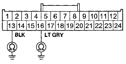
Wire side of female terminals
Is there continuity? YES
-Repair a short to body ground in the wire(s) between the HVAC control unit and the mode control m o t o r . NO
-Go to step 9.
9. Check for continuity between HVAC control unit 24P connector terminals No. 13 and No. 16.
HVAC CONTROL UNIT 24P CONNECTOR
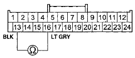
Wire side of female terminals
Is there continuity? YES-
Repair a short in the w i r e s . NO
-Go to step 10.
10. Turn the ignition switch to ON (II), and check the same terminals for voltage between each terminal and body ground.
HVAC CONTROL UNIT 24P CONNECTOR

Wire side of female terminals
Is there any voltage? YES
-Repair a short to power in the wire(s) between the HVAC control unit and the mode control motor.
This short may also damage the HVAC control unit.
Repair a short to power before replacing the HVAC control unit.
NO
-Substitute a known-good HVAC control unit and recheck. If the symptom/indication goes away and the mode control motor runs, replace the original HVAC control unit (see page 21-65).
DTC indicator 6:
A Problem in the Mode Control Linkage, Door, or Motor Circuit
'08-10 models with M/T and '08-09 models 2-door with A/T
1. T u r n the ignition switch to LOCK (0), and then to ON (II).
2. Do the self-diagnostic function with the HVAC control unit (see page 21-9).
3. Check for DTCs.
Is DTC 6 indicated? YES
-Go to step 4.
NO
-lntermittent failure. Check for loose wires or poor connections on the mode control motor circuit.
4. Turn the ignition switch to LOCK (0).
5. Test the mode control motor (see page 21-61).
Is the mode control motor OK? YES
-Go to step 6.
NO
-Replace an the mode control motor (see page 21-62), or repair the mode control linkage or door.
6. Disconnect the mode control motor 7P connector.
7. Disconnect the HVAC control unit 24P connector.
8. Check f o r c o n t i n u i t y between the following terminals of the HVAC control unit 24P connector and the mode control m o t o r 7P connector.
24P: 7P:
No. 7 No. 1
No. 8 No. 2
HVAC CONTROL UNIT 24P CONNECTOR
Wire side of female terminals
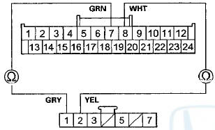
MODE CONTROL MOTOR 7P CONNECTOR
Wire side of female terminals
Is there continuity? YES
-Go to step 9.
NO
-Repair an open in the wire(s) between the HVAC control unit and the mode control motor.
9. Check for continuity between body ground and HVAC control unit 24P connector terminals No. 7 and No. 8 individually.
HVAC CONTROL UNIT 24P CONNECTOR
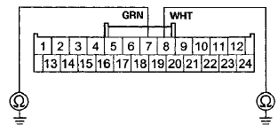
Wire side of female terminals
Is there continuity? YES
-Repair a short to body ground in the wire(s) between the HVAC control unit and the mode control m o t o r . NO
-Substitute a known-good HVAC control unit, and recheck. If the symptom/indication goes away, replace the original HVAC control unit (see page 21-65).
DTC indicator 7;
An Open in the Recirculation Control Motor Circuit
'08-1 В§ models with M/T and '08-09 models 2-door with A/T
1. Turn the ignition switch to LOCK (0), and then to ON (II).
2. Do the self-diagnostic function with the HVAC control unit (see page 21-9).
3. Check for DTCs.
Is DTC 7 indicated? YES
-Go to step 4.
NO
-lntermittent failure. Check for loose wires or poor connections on the recirculation control motor circuit.
4. Turn the ignition switch to LOCK (0).
5. Test the recirculation control motor (see page 21-63).
Is the recirculation control motor OK? YES
-Go to step 6.
NO
-Replace the recirculation control motor (see page 21-64J.
6. Disconnect the recirculation control motor 7P connector.
7. Disconnect the HVAC control unit 24P connector.
8. Check for continuity between the following terminals of the HVAC control unit 24P connector and the recirculation control motor 7P connector.
24P: 7P:
No. 13 No. 7
No. 15 No. 5
No. 20 No. 3
HVAC CONTROL UNIT 24P CONNECTOR
Wire side of female terminals
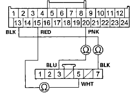
RECIRCULATION CONTROL MOTOR 7P CONNECTOR
Wire side of female terminals
Is there continuity? YES
-Check for loose wires or poor connections at the HVAC control unit 24P connector, and at the recirculation control motor 7P connector. If the connections are good, substitute a known-good HVAC control unit and recheck. If the symptom/indication goes away, replace the original HVAC control unit (see page 21-65).
NO
-Repair an open in the wire(s) between the HVAC control unit and the recirculation control motor.
DTC indicator 8:
A Short in the Recirculation Control Motor Circuit
'В§8-1 В§ models with M/T and '08-09 models 2-door with A/T
1. Turn the ignition switch to LOCK (0), and then to ON (II).
2. Do the self-diagnostic function with the HVAC control unit (see page 21-9).
3. Check for DTCs.
Is DTC 8 indicated? YES
-Go to step 4.
NO
-lntermittent failure. Check for loose wires or poor connections on the icuiioulation control motor circuit.
4. Turn the ignition switch to LOCK (0).
5. Test the recirculation control motor (see page 21-63).
Is the recirculation control motor OK? YES-
Go to step 6.
NO
-Replace the recirculation control motor (see page 21-64).
6. Disconnect the recirculation control motor 7P connector.
7. Disconnect the HVAC control unit 24P connector.
8. Check for continuity between body ground and HVAC control unit 24P connector terminals No. 13 and No.
20 individually.
HVAC CONTROL UNIT 24P CONNECTOR
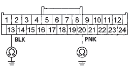
Wire side of female terminals
Is there continuity? YES
-Repair a short to body ground in the wire(s) between the HVAC control unit and the recirculation control motor.
NO
-Go to step 9.
9. Check for continuity between HVAC control unit 24P connector terminals No. 13 and No. 20.
HVAC CONTROL UNIT 24P CONNECTOR
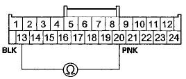
Wire side of female terminals
Is there continuity? YES
-Repair a short in the wires.
NO
-Go to step 10.
10. Turn the ignition switch to ON (II), and check the same terminals for voltage between each terminal and body ground.
HVAC CONTROL UNIT 24P CONNECTOR
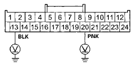
Wire side of female terminals
Is there any voltage? YES
-Repair a short to power in the wire(s) between the HVAC control unit and the recirculation control motor. This short may also damage the HVAC control unit, a Repair short to power before replacing the HVAC control unit.
NO
-Substitute a known-good HVAC control unit and recheck. If the symptom/indication goes away and the recirculation control motor runs, replace the original HVAC control unit (see page 21~65).
DTC indicator 9:
A Problem in the Recirculation Control Linkage, Door, or Motor Circuit
'08-10 modeis with M/T and '08-09 models 2-door with A/T
1. Turn the ignition switch to LOCK (0), and then to ON (II).
2. Do the self-diagnostic function with the HVAC control unit (see page 21-9).
3. Check for DTCs.
Is DTC 9 indicated? YES
-Go to step 4.
NO
-lntermittent failure. Check for loose wires or poor connections on the recirculation control motor circuit.
4. Turn the ignition switch to LOCK (0).
5. Test the recirculation control motor (see page 21-63).
Is the recirculation control motor OK? YES
-Go to step 6.
NO
-Replace the recirculation control motor (see page 21-64), or repair the recirculation control linkage or door.
6. Disconnect the recirculation control motor 7P connector.
7. Disconnect the HVAC control unit 24P connector
8. Check for continuity between the following terminals of the HVAC control unit 24P connector and the recirculation control motor 7P connector.
24P: 7P:
No. 9 No. 2
No. 10 No. 1
HVAC CONTROL UNIT 24P CONNECTOR
Wire side of female terminals
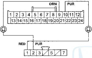
RECIRCULATION CONTROL MOTOR 7P CONNECTOR
Wire side of female terminals
Is there continuity? YES
~Go to step 9.
NO
-Repair an open in the wire(s) between the HVAC control unit and the recirculation control motor.
9. Check for continuity between body ground and HVAC control unit 24P connector terminals No. 9 and No. 10 individually.
HVAC CONTROL UNIT 24P CONNECTOR
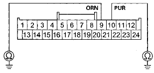
Wire side of female terminals
Is there continuity? YES-Repair a short to body ground in the wire(s) between the HVAC control unit and the recirculation control motor.
NO-Substitute a known-good HVAC control unit, and recheck. If the symptom/indication goes away, replace the original HVAC control unit {see page 21-65).
DTC indicator 10:
An Open or Short In the Mode Control Motor Circuit
'OS-OS models 4-door with A/T and 10 model with A/T
1. Turn the ignition switch to LOCK (0), and then to ON (II).
2. Do the self-diagnostic function with the HVAC control unit (see page 21-9).
3. Check for DTCs.
Is DTC 10 indicated? YES
-Go to step 4.
NO
-lntermittent failure. Check for loose wires or poor connections on the mode control motor circuit.
4. Turn the ignition switch to LOCK (0).
5. Test the mode control motor (see page 21-61).
Is the mode control motor OK? YES
-Go to step 6.
NO
-Replace the mode control motor (see page 21-62).
6. Disconnect the mode control motor IP connector.
7. Disconnect the HVAC control unit 24P connector.
8. Check for continuity between the following terminals of the HVAC control unit 24P connector and the mode control motor 7P connector.
24P: 7P:
No. 1 No. 3
No. 2 No. 4
No. 3 No. 5
No. 4 No. 6
No. 15 No. 7
HVAC CONTROL UNIT 24P CONNECTOR
Wire side of female terminals
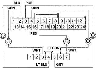
MODE CONTROL MOTOR 7P CONNECTOR
Wire side of female terminals
Is there continuity? YES-
Go to step 9. NO-
Repair an open in the wire(s) between the HVAC control unit and the mode control motor.
9. Check for continuity between body ground and HVAC control unit 24P connector terminals No. 1,2,3, and 4 individually.
HVAC CONTROL UNIT 24P CONNECTOR
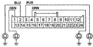
Wire side of female terminals
Is there continuity? YES
-Repair a short to body ground in the wire(s) between the HVAC control unit and the mode control motor.H NO
-Go to step 10.
10. Check for continuity between the HVAC control unit 24P connector terminals as follows.

Is there continuity between any of the terminals? YES
-Repair a short in the w i r e s . NO
-Go to step 11.
11. Turn the ignition switch to ON (II), and check the same terminals for voltage between each terminal and body ground.
HVAC CONTROL UNIT 24P CONNECTOR
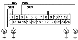
Wire side of female terminals
Is there any voltage?
YES
-Repair a short to power in the wire(s) between the HVAC control unit and the mode control motor.
This short may also damage the HVAC control unit.
Repair a short to power before replacing the HVAC control unit.
NO
-Check for loose wires or poor connections at the HVAC control unit 24P connector, and at the mode control motor 7P connector. If the connections are good, substitute a known-good HVAC control unit, and recheck. If the symptom/indication goes away, replace the original HVAC control unit (see page 21-65).
DTC indicator 11:
A Problem in the Mode Control Linkage, Doors, or Motor Circuit
'08-09 models 4-door with A/T and "10 model with A/T
1. Turn the ignition switch to LOCK (0), and then to ON (tl).
2. Do the self-diagnostic function with the HVAC control unit (see page 21-9).
3. Check for DTCs.
Is DTC 11 indicated?
YES
-Go to step 4.
NO
-lntermittent failure. Check for loose wires or poor connections on the mode control motor circuit.
4. Turn the ignition switch to LOCK (0).
5. Test the mode control motor (see page 21-61).
Is the mode control motor OK?
YES
-Go to step 6.
NO
-Replace the mode control motor (see page 21-62), or repair the mode control linkage or doors.
6. Disconnect the mode control motor 7P connector.
7. Disconnect the HVAC control unit 24P connector.
8. Check for continuity between the following terminals of the HVAC control unit 24P connector and the mode control motor 7P connector.
24P: 7P:
No. 7 No. 1
No. 8 No. 2
HVAC CONTROL UNIT 24P CONNECTOR
Wire side of female terminals
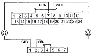
MODE CONTROL MOTOR 7P CONNECTOR
Wire side of female terminals
Is there continuity?
YES
-Go to step 9.
NO
-Repair an open in the wire(s) between the HVAC control unit and the mode control motor.
9. Check for continuity between body ground and HVAC control unit 24P connector terminals No. 7 and No. 8 individually.
HVAC CONTROL UNIT 24P CONNECTOR
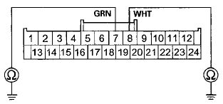
Wire side of female terminals
Is there continuity? YES
-Repair a short to body ground in the wire(s) between the HVAC control unit and the mode control motor.
NO
-Substitute a known-good HVAC control unit, and recheck. If the symptom/indication goes away, replace the original HVAC control unit (see page 21-65).
DTC indicator 12:
A Problem in the Blower Motor Circuit
1. Turn the ignition switch to LOCK (0), and then to ON (II).
2. Do the self-diagnostic function with the HVAC control unit (see page 21-9).
3. Check for DTCs.
Is DTC 12 indicated?
YES
-Go to step 4.
NO
-lntermittent failure. Check for loose wires or poor connections on the blower motor circuit.
4. Turn the ignition switch to LOCK (0).
5В» Check the No, 8 (40 A) fuse in the under-hood fuse/relay box, and the No. 16 (7.5 A) fuse in the driver's under-dash fuse/relay box.
Are the fuses OK?
YES
-Go to step 6.
NO
-Replace the fuse(s), and recheck. If the fuse(s) blow again, check for a short in the No. 8 (40 A) fuse and the No. 16 (7.5 A) fuse circuits.
6. Disconnect the blower motor 2P connector.
7. Turn the ignition switch to ON (II).
8. Measure the voltage between blower motor 2P connectorterminal No. 1 and body ground.
BLOWER MOTOR 2P CONNECTOR

Wire side of female terminals
Is there battery voltage?
YES-
Go to step 9.
NO
-Go to step 28.
9. Turn the ignition switch to LOCK (0).
10. Reconnect the blower motor 2P connector.
11. Connect blower motor 2P connector terminal No. 2 to body ground with a jumper wire.
BLOWER MOTOR 2P CONNECTOR
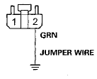
Wire side of female terminals
12. Turn the ignition switch to ON (II).
Does the blower motor run? YES
-Go to step 13.
NO
-Replace the blower motor (see page 21-67).
13. Turn the ignition switch to LOCK (0).
14. Disconnect the jumper wire.
15. Disconnect the power transistor 4P connector.
16. Check for continuity between power transistor 4P connector terminal No. 2 and body ground.
POWER TRANSISTOR 4P CONNECTOR

Wire side of female terminals
Is there continuity?
YES-
Go to step 17.
NO
-Check for an open in the wire between the power transistor and body ground. If the wire is OK, check for poor ground at G302 (see page 22-30).
17. Connect power transistor 4P connector terminals No.
2 and No. 4 with a jumper wire.
POWER TRANSISTOR 4P CONNECTOR

Wire side of female terminals
18. Turn the ignition switch to ON (II).
Does the blower motor run at high speed?
YES
-Go to step 19.
NO
-Repair an open in the GRN wire between the power transistor and the blower motor.B 19. Turn the ignition switch to LOCK (0).
20. Disconnect the jumper wire.
21. Disconnect the HVAC control unit 24P connector.
22. Check for continuity between body ground and HVAC control unit 24P connector terminals No. 18 and No.
19 individually.
HVAC CONTROL UNIT 24P CONNECTOR
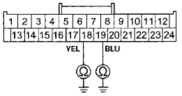
Wire side of female terminals
Is there continuity? YES
-Repair a short to body ground in the wire(s) between the HVAC control unit and the power transistor.
NO
-Go to step 23.
23. Check for continuity between the following terminals of the HVAC control unit 24P connector and the power transistor 4P connector.
24P: 4P:
No. 18 No. 1
No. 19
No. 3
HVAC CONTROL UNIT 24P CONNECTOR
Wire side of female terminals
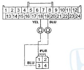
POWER TRANSISTOR 4P CONNECTOR
Wire side of female terminals
Is there continuity?
YES
-Go to step 24.
NO
-Repair an open in the wire(s) between the HVAC control unit and the power transistor.
24. Turn the ignition switch to ON (II).
25. Measure the voltage between body ground and HVAC control unit 24P connector terminals No. 18 and No.
19 individually.
HVAC CONTROL UNIT 24P CONNECTOR
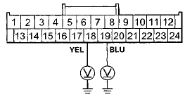
Wire side of female terminals
Is there any voltage?
YES
-Repair a short to power in the wires.I NO
-Go to step 26.
26. Reconnect the HVAC control unit 24P connector.
27. Test the power transistor (see page 21-58).
Is the power transistor OK?
YES-
Check for loose wires or poor connections at the HVAC control unit 24P connector, and at the power transistor 4P connector. If the connections are good, substitute a known-good HVAC control unit, and recheck. If the symptom/indication goes away, replace the original HVAC control unit (see page 21-65).
NO
-Replace the power transistor.
28. Turn the ignition switch to LOCK (0).
29. Disconnect the jumper wire.
30. Remove the blower motor relay from the under-hood fuse/relay box, and test it (see page 22-93).
Is the relay OK?
YES
-Go to step 31.
NO
-Replace the blower motor relay.
31. Measure the voltage between blower motor relay 4P socket terminal No. 1 and body ground.
BLOWER MOTOR RELAY 4P SOCKET
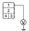
Terminal side of female terminals
Is there battery voltage?
YES
-Go to step 32.
NO
-Replace the under-hood fuse/relay box (see page 22-85).
32. Turn the ignition switch to ON (II).
33. Measure the voltage between blower motor relay 4P socket terminal No. 4 and body ground.
BLOWER MOTOR RELAY 4P SOCKET

Terminal side of female terminals
Is there battery voltage?
YES
-Go to step 34.
NO-
Repair an open in the wire between the No. 16 (7.5 A) fuse in the driver's under-dash fuse/relay box and the blower motor relay.
34. Turn the ignition switch to LOCK (0).
35. Check for continuity between blower motor relay 4P socket terminal No. 3 and body ground.
BLOWER MOTOR RELAY 4P SOCKET

Terminal side of female terminals
Is there continuity? YES
-Repair an open in the WHT wire between the blower motor relay and the blower motor.
NO
-Check for an open in the wire between the blower motor relay and body ground. If the wire is OK, check for poor ground at G301 (see page 22-28)
DTC indicator 13:
HVAC Control Unit Internal Error
NOTE: Check the battery condition (see page 22-90) and the charging system (see page 4-25).
1. Turn the ignition switch to LOCK (0), and then to ON (II).
2. Do the self-diagnostic function with the HVAC control unit (see page 21-9).
3. Check for DTCs.
Is DTC 13 indicated? YES
-The HVAC control unit is faulty, replace the HVAC control unit (see page 21-65).
NO
-lntermittent failure, the HVAC control unit is OK at this time. Check for poor connections at the HVAC control unit and at G401 (see page 2 2 4 0 ).
DTC indicator 14:
An Open in the Evaporator .
Temperature Sensor Circuit
1. Turn the ignition switch to LOCK (0), and then to ON (II).
2. Do the self-diagnostic function with the HVAC control unit (see page 21-9).
3. Check for DTCs.
Is DTC 14 indicated? YES
-Go to step 4.
NO
-lntermittent failure. Check for loose wires or poor connections on the evaporator temperature sensor c i r c u i.
4. Turn the ignition switch to LOCK (0).
5. Remove the evaporator temperature sensor (see page 21-67) and test it (see page 21-58).
Is the evaporator temperature sensor OK? YES
-Go to step 6.
NO
-Replace the evaporator temperature sensor (see page 21-67).
6. Disconnect the HVAC control unit 24P connector.
7. Check for continuity between HVAC control unit 24P connector terminal No. 14 and evaporator temperature sensor 2P connector terminal No. 2.
HVAC CONTROL UNIT 24P CONNECTOR
Wire side of female terminals
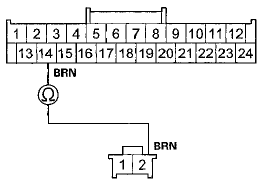
EVAPORATOR TEMPERATURE SENSOR 2P CONNECTOR
Wire side of female terminals
Is there continuity? YES
-Go to step 8.
NO
-Repair an open in the wire between the HVAC control unit and the evaporator temperature s e n s o r .
8. Check for continuity between HVAC control unit 24P connector terminal No. 15 and evaporator 1 temperature sensor 2P connector terminal No. 1.
HVAC CONTROL UNIT 24P CONNECTOR
Wire side of female terminals
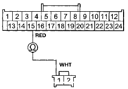
EVAPORATOR TEMPERATURE SENSOR 2P CONNECTOR
Wire side of female terminals
Is there continuity? YES
-Check for loose wires or poor connections at the HVAC control unit 24P connector, and at the evaporator temperature sensor 2P connector. If the connections are good, substitute a known-good HVAC control unit and recheck. If the symptom/indication goes a w a y , replace the original HVAC control unit (see page 21-65).
NO
-Repair an open in the wire between the HVAC control unit and the evaporator temperature sensor.
DTC indicator 15:
A Short in the Evaporator Temperature Sensor Circuit
1. Turn the ignition switch to LOCK (OL and then to ON (II).
2. Do the self-diagnostic function with the HVAC control unit (see page 21-9).
3. Check for DTCs.
Is DTC 15 indicated? YES
-Go to step 4.
NO
-lntermittent failure. Check for damaged wires or connections in the evaporator temperature sensor circui.
4. Turn the ignition switch to LOCK (0).
5. Remove the evaporator temperature sensor (see page 21-67) and test it (see page 21-58).
Is the evaporator temperature sensor OK? YES
-Go to step 6.
NO
-Replace the evaporator temperature sensor (see page21-67).B 6. Disconnect the HVAC control unit 24P connector.
7. Check for continuity between body ground and HVAC control unit 24P connector terminal No. 14.
HVAC CONTROL UNIT 24P CONNECTOR
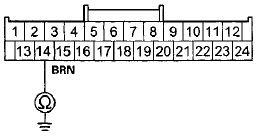
Wire side of female terminals
Is there continuity? YES
-Repair a short to body ground in the wire between the HVAC control unit and the evaporator temperature sensor.
NO
-Go to step 8.
8. Check for continuity between HVAC control unit 24P connectorterminal No. 14and No. 15.
HVAC CONTROL UNIT 24P CONNECTOR
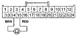
Wire side of female terminals
Is there continuity? YES
-Repair a short in the wires between the HVAC control unit and the evaporator temperature sensor.
NO
-Substitute a known-good HVAC control unit, and recheck. If the symptom/indication goes away, replace the original HVAC control unit (see page 21-65).
 Circuit Diagram
'08-09 Models
10 Model
...
 Recirculation Control Motor Circuit
Troubleshooting
908-09 models 4-door with A/T and '10 model
with AT
1. Check the No. 16 (7.5 A) fuse in the driver's
under-dash fuse/ relay box.
Is the fuse OK?
YES-Go to step 2.
NO-Replace the fuse, and re ...
See also:
Shift Lock Stop/Shift Lock Stop Cushion
Replacement
Type A Shift Lever
1. Remove the shift lock solenoid (see page 14-254).
2. Remove the shift lock stop (A) and the stop cushion
(B) as a set.
3. Apply silicone grease to the pin (C) of the shif ...
Trunk Lid Adjustment
1. Remove the rear shelf (see page 20-128).
2. Pry up the notches (A) to release the rear hooks (B), and pull up the cap (C)
to release the side hooks (D), then remove
the cap.
3. Slightly lo ...
Emblem/Sticker Replacement
2-door
NOTE: When removing emblems/sticker, take care not to scratch the body.
1. To remove the front "H" emblem, remove the front bumper (see page 20-255).
2. Clean the body surfaces ...
