 Honda Accord: Driver's Seat Position Sensor Replacement
Removal (Power seat)
NOTE: Do not t u r n t h e i g n i t i o n s w i t c h t o ON (II), a n d do not connect t h e battery cable w h i l e r e m o v i n g t he d r i v e r ' s seat p o s i t i o n sensor.
1. Raise t h e seat all t he w a y up.
2. Do t h e b a t t e r y terminal disconnection procedure (see page 22-91), t h e n w a i t at least 3 m i n u t e s before s t a r t i ng work.
3. Remove t h e f r o n t d r i v e r ' s seat (see page 20-194).
4. Disconnect t h e d r i v e r ' s seat w i r e harness 2P connector (A) f r om t h e d r i v e r ' s seat p o s i t i o n sensor (B).
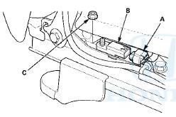
5. Remove t h e nut (C), t h e n remove t h e d r i v e r ' s seat p o s i t i o n sensor.
Installation (Power seat)
NOTE: • Be s u r e t o install t h e harness so it does not pinched or i n t e r f e re w i t h other parts.
• Do not t u r n t h e i g n i t i on s w i t c h t o ON (II), a n d d o not connect t h e battery cable w h i l e i n s t a l l i ng t he d r i v e r 's seat p o s i t i o n sensor.
1. Install t h e d r i v e r ' s seat p o s i t i o n sensor (A) w i t h a nut (B), t h e n connect t h e d r i v e r ' s seat w i r e harness 2P connector (C) t o t h e d r i v e r ' s seat p o s i t i o n sensor.
2. Reinstall t h e f r o n t d r i v e r ' s seat (see page 20-194).
3. Do t h e battery terminal reconnection procedure (see page 22-91).
4. Clear any DTCs w i t h t he HDS (see page 24-38).
5. Check t h e o p e r a t i o n of t he d r i v e r ' s seat p o s i t i on sensor w i t h t h e HDS (see page 24-43).
6. C o n f i rm proper SRS o p e r a t i o n : T u r n t h e i g n i t i on s w i t c h t o ON (II); t h e SRS indicator s h o u l d come on f o r about 6 seconds and t h e n g o off.
Removal (Manual seat)
NOTE: Do not t u r n t h e i g n i t i o n s w i t c h t o ON (II), a n d do not connect t h e battery cable w h i l e r e m o v i n g t he d r i v e r ' s seat p o s i t i o n sensor.
1. Raise t h e seat all t h e w a y up.
2. Do t h e b a t t e r y t e r m i n a l d i s c o n n e c t i o n procedure (see page 22-91), t h e n w a i t at least 3 m i n u t e s before s t a r t i n g work.
3. Remove t h e f r o n t d r i v e r ' s seat (see page 20-194).
4. Remove t h e recline cover (see page 20-208).
5. Disconnect t h e d r i v e r ' s seat p o s i t i o n sensor harness 2P c o n n e c t o r (A) f r o m t h e driver ' s seat position sensor (B).
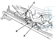
6. Remove t h e TORX b o l t (C) u s i n g a TORX T30 b i t , t h en remove t h e d r i v e r ' s seat p o s i t i o n sensor.
Installation (Manual seat)
NOTE: • Be s u r e t o install t h e harness so it does not p i n c h e d or i n t e r f e re w i t h other parts.
• Do not t u r n t h e i g n i t i o n s w i t c h t o O N (II), a n d d o not connect t h e battery cable w h i l e i n s t a l l i ng t h e d r i v e r 's seat p o s i t i o n sensor.
1. Install t h e d r i v e r ' s seat p o s i t i o n sensor (A) w i t h a n ew TORX bolt (B), u s i n g a TORX T30 bit. Connect t he d r i v e r ' s seat p o s i t i o n sensor harness 2P connector (C) t o t h e d r i v e r ' s seat p o s i t i o n sensor.
2. Install t h e recline cover (see page 20-208).
3. Install t h e f r o n t d r i v e r ' s seat (see page 20-194).
4. Do t h e battery t e r m i n a l reconnection procedure (see page 22-91).
5. Clear any DTCs w i t h t h e HDS (see page 24-38).
6. Check t h e o p e r a t i o n of t h e d r i v e r ' s seat p o s i t i on sensor w i t h t h e HDS (see page 24-43).
7. C o n f i rm proper SRS o p e r a t i o n : T u r n t h e i g n i t i on s w i t c h t o ON (II); t h e SRS indicator s h o u l d c o m e on f o r about 6 seconds and t h e n go off.
 Front Impact Sensor Replacement
Removal
1. Do t h e battery t e r m i n a l d i s c o n n e c t i o n procedure (see
page 22-91), t h e n w a i t at least 3 m i n u t e s before
s t a r t i ng work.
2. Remove t h e f r o n t b ...
 Passenger's Airbag Cutoff Indicator Replacement
1. With navigation: Remove the dashboard center vent
(see page 20-178).
2. Without navigation: Remove the audio unit (see page
23-114).
3. Disconnect the 6P connector (A) from the passenger's
...
See also:
Operating the XM Radio
To listen to XM Radio, turn the
ignition switch to the ACCESSORY
(I) or ON (II) position, and press the
button. The last channel you
listened to will show in the audio
screen and the cent ...
Owner’s Maintenance Checks
You should check the following
items at the specified intervals. If
you are unsure of how to perform
any check, turn to the appropriate
page listed.
Engine oil level Check every
time you fi ...
Fuel Recommendation
Your vehicle is designed to operate
on unleaded gasoline with a pump
octane number of 87 or higher. Use
of a lower octane gasoline can cause
a persistent, heavy metallic rapping
noise that c ...