 Honda Accord: Door Lock Knob Switch Test
Driver's Door
1. Remove the driver's door panel (see page 20-17).
2. Disconnect the 10P connector (A) from the door lock actuator (B).
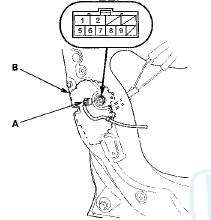
3. Check for continuity between the terminals.
• There should be continuity between terminals No. 6 and No. 5 when the door lock knob switch is in the LOCK position and no continuity when the switch is in the UNLOCK position.
• There should be continuity between terminals No. 7 and No. 5 when the door lock knob switch is in the UNLOCK position and no continuity when the switch is in the LOCK position.
4. If the continuity is not as specified, replace the door lock actuator.
Passenger Doors (With Security)
1. Remove the passenger's door panel.
• Front (see page 20-17) • Rear (see page 20-38) 2. Disconnect the 10P connector (A) from the door lock actuator (B).
3. Check for continuity between the terminals.
There should be continuity between terminals No. 8 [No. 7] and No. 10 [No. 5] when the door lock knob switch in the UNLOCK position and no continuity when the switch is in the LOCK position.
[ ] : Left rear door
4. If the continuity is not specified, replace the door lock actuator.
 Door Lock Actuator Test
Driver's Door and Left Rear Door (4-door)
1 Remove the door panel.
• Front (see page 20-17)
• Rear (see page 20-38)
2. Disconnect the 10P connector (A) from the actuator
(B).
NOTE: T ...
 Door Key Cylinder Switch Test
1. Remove the driver's door panel (see page 20-17).
2. Disconnect the 10P connector (A) from the door lock
actuator (key cylinder switch) (B).
3. Check for continuity between the terminals.
...
See also:
Wiper Blades
Check the condition of the wiper
blades at least every six months.
Replace them if you find signs of
cracking in the rubber, areas that are
getting hard, or if they leave streaks
and unwiped ...
Refilling Window Washer Fluid
Check the amount of window washer fluid by looking at the reservoir.
If the level is low, fill the washer reservoir.
If the washer fluid is low, the washer level
indicator comes on.
Pour the ...
Dashboard/Steering Hanger Beam
Disassembly/Reassembly
Special Tools Required
KTC Trim Tool Set SOJATP2014*
*Available through the Honda Tool and
Equipment
Program; call 888-424-6857
NOTE:
- Put on gloves to protect your hands.
В© Take care no ...