 Honda Accord: Countershaft Bearing Replacement
Special Tools Required
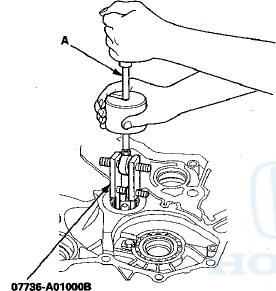
-Adjustable Bearing Puller, 2 5 - 4 0 mm 07736-A01000B
-Driver Handle, 15 x 135L 07749-0010000
-Attachment, 62 x 68 mm 07746-0010500
1. Remove the countershaft bearing using the 25—40 mm adjustable bearing puller and a commercially available 3/8 "-16 slide hammer (A).
2. Remove the ATF guide plate (A), and check it for wear and damage. If the guide plate is worn or damaged, replace it.

3. Install the ATF guide plate in the torque converter housing, and install a new countershaft bearing (B).
4. Install the countershaft bearing securely in the torque converter housing using the driver handle and the 62 x 68 mm attachment.
5. Make sure that the bearing outer race notch-cut (A) is installed at a height of 0—0.05 mm (0—0.002 in) (B) above the torque converter housing surface (C). Do not install the countershaft bearing higher than 0.05 mm (0.002 in) above the torque converter housing surface.
 Mainshaft Bearing and Oil Seal
Replacement
Mainshaft Bearing and Oil Seal
Replacement
Special Tools Required
-Adjustable Bearing Puller, 2 5 - 4 0 mm 07736-A01000B
-Driver Handle, 15 x 135L 07749-0010000
-Attachment, 62 x 68 mm 07746-0010500
-Attachment, 72 x 75 mm 07746-0010600
1 ...
 Secondary Shaft Bearing
Replacement
Secondary Shaft Bearing
Replacement
Special Tools Required
•Driver Handle, 15 x 135L 07749-0010000
•Attachment, 62 x 68 mm 07746-0010500
1. Remove the set plate bolt, then remove the lock
washer (A) and the bearing set pla ...
See also:
Brake System Inspection and Test
Inspect the brake system components listed. Repair or replace any parts that
are leaking or damaged.
Component Inspections:
Brake System Test
Brake pedal sinks/fades when braking
1. Set the pa ...
Circuit Diagram
...
To Stop Playing Your iPod
To play the radio, press the FM/AM,
or button. Press the CD button
to switch to the disc mode. Press the
AUX button to switch back to the
iPod.
Disconnecting an iPod
You can disconnect the ...