
 Honda Accord: Cf Under Head Removal
NOTE: - Use fender covers to avoid damaging painted surfaces.
- To avoid damage, unplug the wiring connectors carefully while holding the connector portion.
- Connect the Honda Diagnostic System (HDS) to the data link connector (DLC), and monitor the engine coolant temperature (ECT) sensor 1. To avoid damaging the cylinder head, wait until the ECT sensor 1 temperature drops below 100 Р’В°F (38 Р’В°C) before loosening the cylinder head bolts.
- Mark all wiring and hoses to avoid misconnection.
Also, be sure that they do not contact other wiring or hoses, or interfere with any other parts.
1. Remove the strut brace (if equipped) (see page 20-306).
2. Relieve the fuel pressure (see page 11-306).
3. Drain the engine coolant (see page 10-6).
4. Remove the drive belt (see page 4-30).
5. Remove the intake manifold (see page 9-4).
6. Remove the catalytic converter (see page 11-339).
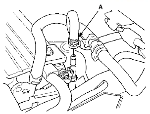
7. Disconnect the evaporative emission (EVAP) canister hose (A).
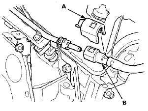
8. Remove the quick-connect fitting cover (A), then disconnect the fuel feed hose (B) (see page 11-314).
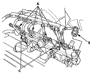
9. Disconnect the four fuel injector connectors (A), the engine mount control solenoid valve connector (B), and remove the ground cables (C).
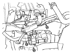
10. Remove the four bolts securing the EVAP canister purge valve bracket.
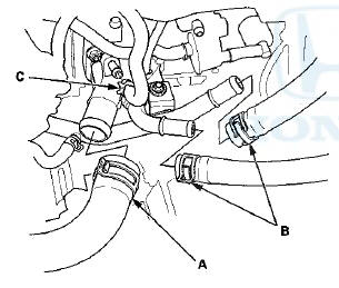
11. Disconnect the upper radiator hose (A), the heater hoses (B), and the water bypass hose (C).
12. Remove the two bolts (A) securing the connecting pipe.
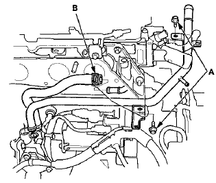
13. Disconnect the water bypass hose (B).
14. Disconnect the following engine wire harness connectors, and remove the wire harness clamps from the cylinder head:
- Engine coolant temperature (ECT) sensor 1 connector
- Camshaft position (CMP) sensor A (Intake) connector
- Camshaft position (CMP) sensor B (Exhaust) connector
- Two rocker arm oil control solenoid connectors
- Two rocker arm oil pressure switch connectors
- EVAP canister purge valve connector
- Variable valve timing control (VTC) oil control solenoid valve connector
- Engine oil pressure switch connector
15. Remove the cam chain (see page 6-62).
16. Remove the rocker arm assembly (see page 6-81).
17. Remove the cylinder head bolts. To prevent warpage, loosen the bolts in sequence 1/3 turn at a time; repeat the sequence until all bolts are loosened.
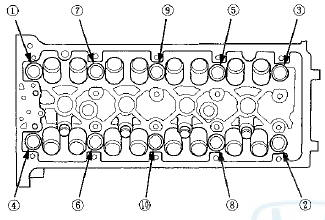
18. Remove the cylinder head.
 Cylinder Head Cover Installation
1. Thoroughly clean the head cover gasket and the
groove.
2. Install the head cover gasket (A) in the groove of the
cylinder head cover (B).
3. Check that the mating surfaces are clean and dry ...
 CMP Pulse Plate A Replacement
1. Remove the cylinder head cover (see page 6-73).
2. Remove camshaft position (CMP) sensor A (see page
11-274).
3. Hold the camshaft with an open-end wrench, then
loosen the bolt.
4. Remov ...
See also:
Audio Disc Changer
Removal/Installation
With Navigation
NOTE:
• Put on gloves to protect your hands.
• Take care not to scratch the dashboard and related
parts.
• Lay a shop towel under the parts when working on
the ...
Circuit Diagram
...
Using a Booster Seat
A child who has outgrown a forwardfacing
child seat should ride in a
back seat and use a booster seat
until the lap/shoulder belt fits them
properly without the booster.
Some states, Canadi ...