 Honda Accord: ATF Pump Inspection
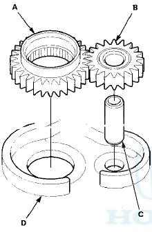
1. Install the ATF pump drive gear (A), the driven gear (B), and the ATF pump driven gear shaft (C) in the main valve body (D). Lubricate all parts with ATF, and install the ATF pump driven gear with its grooved and chamfered side facing up.
2. Measure the side clearance of the ATF pump drive gear (A) and the driven gear (B).
ATF Pump Gears Side (Radial) Clearance
Standard (New)
ATF Pump Drive Gear:
0.210-0.265 mm (0.0083-0.0104 in)
ATF Pump Driven Gear:
0.070-0.125 mm (0.0028-0.0049 in)
3. Remove the ATF pump driven gear shaft. Measure the thrust clearance between the ATF pump driven gear (A) and the main valve body (B) using a straight edge (C) and a feeler gauge (D).
ATF Pump Drive/Driven Gear Thrust (Axial) Clearance
Standard (New): 0.03-0.06 mm (0.001 -0.002 in)
Service Limit: 0.07 mm (0.0003 in)
 Main Valve Body Disassembly,
Inspection, and Reassembly
Main Valve Body Disassembly,
Inspection, and Reassembly
1. Clean all parts thoroughly in solvent, and dry them with compressed air.
Blow out all passages.
2. Do not use a magnet to remove the check balls, it may magnetize the balls.
3. Inspect the ...
 Regulator Valve Body Disassembly,
Inspection, and Reassembly
Regulator Valve Body Disassembly,
Inspection, and Reassembly
1. Clean all parts thoroughly in solvent and dry them with compressed air.
Blow out all passages.
2. Inspect the valve body for scoring and damage.
3. Check all valves for free movement. If an ...
See also:
ATF Cooler Cleaning
Special Tools Required
•ATF Cooler Cleaner GHTTTCF6H
-Magnetic Nonbypass Spin-On Filter GTHGNBP2*
*: Available through the Honda Tool and Equipment
Program 888-424-6857.
Before installing an ...
Cruise Control
Maintains a constant vehicle speed without having to keep your foot on the
accelerator. Use cruise control on freeways or open roads where you can travel
at a
constant speed with little accelera ...
Roof and Trunk
...