 Honda Accord: System Description
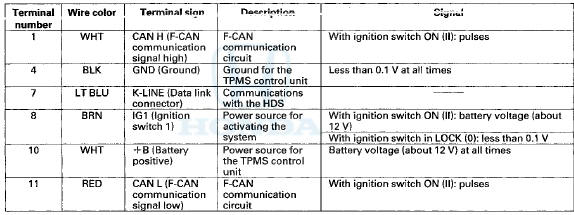
TPMS Control Unit Inputs and Outputs for 20P Connector
Wire side of female terminals
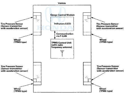
System Structure
Once the vehicle speed exceeds 28 mph (45 km/h), the TPMS control unit monitors all four tire pressure sensors and the system function. If it detects low pressure in a tire, it alerts the driver by turning on the low tire pressure indicator. If it detects a problem in the system, it turns on the TPMS indicator.
TPMS control unit
Mounted over the accelerator pedal module, the TPMS control unit receives wireless tire pressure sensor ID signals every time the vehicle speeds exceeds 28 mph (45 km/h). It also receives wireless signals from the transmitters for tire pressure and the sensor condition, and it continuously monitors and controls the system. The TPMS control unit cannot directly determine the position (location) of a tire pressure sensor(s) on the vehicle since it is a wireless system. Tire pressure sensor locations will change during scheduled vehicle maintenance (tire rotation).
NOTE: To determine the actual location of each tire pressure sensor on the vehicle, do the tire pressure sensor location procedure (see page 18-61). Once the tire pressure sensor locations are identified, write the sensor ID on the side wall of the tire with a tire crayon to eliminate confusion.
Indicators
Two indicators are in the gauge control module: The low tire pressure indicator comes on when any tire pressure is low, and the TPMS indicator that comes on only if there's a problem with the system.
The low tire pressure indicator alerts the driver that a tire(s) pressure is low, but does not specify the tire(s) location.
Tire pressure sensor
Each sensor is an integrated unit made up of the tire valve stem, a tire pressure sensor, and a transmitter. The unit is attached to the inside of the wheel, around the valve stem. The sensor transmits the internal tire information to the TPMS control unit once every 60 seconds when the vehicle speed exceeds 28 mph (45 km/h). When the TPMS control unit receives a tire pressure signal that is less than: 168 kPa (1.7 kgf/cm2,24 psi) with 16 inch wheels, 175 kPa (1.8 kgf/cm2, 25 psi) with 17 inch wheels, the TPMS control unit then turns on the low tire pressure indicator. When that tire's pressure is increased to more than: 190 kPa (1.9 kgf/cm2, 28 psi) with 16 inch wheels, 200 kPa (2.0 kgf/cm2,29 psi) with 17 inch wheels, and the vehicle is driven above 28 mph (45 km/h) the transmitter sends the tire pressure signal to the TPMS control unit, and then the TPMS control unit turns the indicator off.
NOTE: Do not mix the tire pressure sensors or TPMS type wheels with other TPMS types. Be sure to use the correct type sensors and wheels for this system.
Sensor are active: - When the wheel rotates over 28 mph (45 km/h) the sensor detects the momentum, and switches the sensor to the normal function mode.
9 The LF (low frequency) signal of the TPMS tool makes the sensor active even though the vehicle is stopped. The tire pressure sensor goes into sleep mode when the acceleration sensor detects the wheel is stationary for 5 minutes or m u r e .
Wheels
The TPMS will not work unless TPMS type wheels are installed on the vehicle. There are six different types of wheels used.
- Aluminum wheel type: The original equipment wheels have a 'TPMS", "TA0", or "TE0" mark (A) on them. The wheels also have counterweights (B) incorporated on the opposite side of the tire pressure sensor (C), to counterbalance the weight of the sensor.
- Steel wheel type: The original equipment wheels have a "TPMS" mark (A) on them, and a counterweight (B) balances the weight of the tire pressure sensor (C) by a size difference in the wheel disc holes.
Aluminum w h e e l s
System Communication
- When the vehicle is traveling more than 28 mph (45 km/h), an RF (radio frequency) band wave signal is transmitted from each tire pressure sensor to the TPMS control unit.
- When the wheels rotate, the tire pressure sensors momentum is detected, switching them from sleep mode to normal function (awake) mode. After the vehicle is stationary for 5 minutes, the sensors switch from normal function mode back to sleep mode to extend their battery life.
- Each tire pressure sensor has its own ID to prevent jamming by similar systems on other vehicles. After memorizing all the sensor IDs, the TPMS control unit recognizes only those specific signals.
- An ID cannot be memorized automatically. The TPMS control unit knows which ID belongs to each tire pressure sensor. This recurring ID confirmation prevents any confusion in the system as a result of normal tire rotation.
NOTE: Be careful not to bend the brackets oh the TPMS control unit. Misalignment of the TPMS control unit could interfere with sending and receiving signals.
TPMS Control Unit (With an Internal Radio Frequency Antenna)
Tire Pressure Sensor (Sensor-transmitter with acceleration sensor)

 Circuit Diagram
DRIVER'S UNDER-DASH
FUSE/RELAY BOX CONNECTOR N (16P)
Wire side of female terminals
DRIVER'S UNDER-DASH
FUSE/RELAY BOX CONNECTOR P (20P)
Wire side of female terminals
GAUGE CONTROL MODULE 3 ...
See also:
Brake/Clutch Fluid
Use the same fluid for both the brakes and clutch.
• Checking the Brake Fluid
The fluid level should be between the MIN
and MAX marks on the side of the reservoir.
NOTICE
Brake fluid marke ...
Fan Controls
Component Location Index
Symptom Troubleshooting Index
'08-09 models
10 model
Circuit Diagram
'08-09 models
'10 model
Radiator Fan Circuit Troubleshooting
'08-09 models
1 ...
Carrier Bearing Replacement
Special Tools Required
Driver Handle, 40 mm I.D. 07746-0030100
1. Check the carrier bearings for wear and rough
rotation. If they rotate smoothly and their rollers show
no signs of wear, the beari ...