 Honda Accord: DTC Troubleshooting
DTC P0010:
VTC Oil Control Solenoid Valve Malfunction
NOTE: Before you troubleshoot record all freeze data and any on-board snapshot and review the general troubleshooting Information (see page 11-3).
1. Turn the ignition switch to ON (II).
2. Clear the DTC with the HDS.
3. Start the engine. Hold the engine speed at 3,000 rpm without load (A/T in P or N, M/T in neutral) until the radiator fan comes on, then let it idle.
4. Do the VTC TEST in the INSPECTION MENU with the HDS.
5. Check for Pending or Confirmed DTCs with the HDS.
Is DTC P0010 indicated? YES
-Go to step 6.
NO-
lntermittent failure, the system is OK at this time.
Check for poor connections or loose terminals at the VTC oil control solenoid valve and the ECM/PCM.- 6. Turn the ignition switch to LOCK (0).
7. Disconnect the VTC oil control solenoid valve 2P connector.
8. At the solenoid valve side, measure the resistance between VTC oil control solenoid valve 2P connector terminals No. 1 and No. 2.
VTC OIL CONTROL SOLENOID VALVE 2P CONNECTOR

Terminal side of male terminals
Is there 6.75-”8.25 Q at room temperature? YES-Go to step 9.
NO-Go to step 14.
9. Check for continuity between VTC oil control solenoid valve 2P connector terminal No. 1 and body ground.
VTC OIL CONTROL SOLENOID VALVE 2P CONNECTOR
Wire side of female terminals
Is there continuity? YES
-Go to step 10.
NO-
Repair open in the wire between the VTC oil control solenoid valve and G101; M/T (see page 22-20), A/T (see page 22-22), then go to step 15.
10. Jump the SCS line with the HDS.
11. Disconnect ECM/PCM connector C (49P).
12. Check for continuity between ECM/PCM connector terminal C23 and body ground.
ECM/PCM CONNECTOR C (49P)
Terminal side of female terminals
Is there continuity? YES
-Repair short in the wire between the ECM/PCM (C23) and the VTC oil control solenoid valve, then go to step 15.
NO
-Go to step 13.
13. Check for continuity between VTC oil control solenoid valve 2P connector terminal No. 2 and ECM/PCM connector terminal C23.
VTC OIL CONTROL SOLENOID VALVE 2P CONNECTOR
Terminal side of female terminals
Is there continuity? YES
-Go to step 22.
NO
-Repair open in the wire between the ECM/PCM (C23) and the VTC oil control solenoid valve, then go to step 15.
14. Replace the VTC oil control solenoid valve (see page 11-273).
15. Reconnect all connectors.
16. Turn the ignition switch to ON (II).
17. Reset the ECM/PCM with the HDS.
18. Do the ECM/PCM idle learn procedure (see page 11-293).
19. Do the VTC TEST in the INSPECTION MENU with the HDS.
20. Check for Pending or Confirmed DTCs with the HDS.
Is DTC PQ010 indicated? YES
-Check for poor connections or loose terminals at the VTC oil control solenoid valve and the ECM/PCM, then go to step 1.
NO
-Go to step 21.
21. Monitor the OBD STATUS for DTC P0010 in the DTCs MENU with the HDS.
Does the screen indicate PASSED? YES-
Troubleshooting is complete. If any other Pending or Confirmed DTCs were indicated in step 20, go to the indicated DTCs troubleshooting.
NO
-lf the screen indicates FAILED, check for poor connections or loose terminals at the VTC oil control solenoid valve and the ECM/PCM, then go to step 1. If the screen indicates NOT COMPLETED, go to step 19.
22. Reconnect all connectors.
23. Update the ECM/PCM if it does not have the latest software (see page 11-203), or substitute a known-good ECM/PCM (see page 11-7).
24. Do the VTC TEST in the INSPECTION MENU with the HDS.
25. Check for Pending or Confirmed DTCs with the HDS.
Is DTC P0010 indicated? YES
-Check for poor connections or loose terminals at the VTC oil control solenoid valve and the ECM/PCM.
If the ECM/PCM was updated, substitute a known-good ECM/PCM (see page 11 -7), then go to step 24. If the ECM/PCM was substituted, go to step 1.
NO
-Go to step 26.
26. Monitor the OBD STATUS for DTC P0010 in the DTCs MENU with the HDS.
Does the screen indicate PASSED? YES
-lf the ECM/PCM was updated, troubleshooting is complete. If the ECM/PCM was substituted, replace the original ECM/PCM (see page 11-204). If any other Pending or Confirmed DTCs were indicated in step 25, go to the indicated DTCs troubleshooting.
NO-
lf the screen indicates FAILED, check for poor connections or loose terminals at the VTC oil control solenoid valve and the ECM/PCM. If the ECM/PCM was updated, substitute a known-good ECM/PCM (see page 11-7), then go to step 24. If the ECM/PCM was substituted, go to step 1. If the screen indicates NOT COMPLETED, go to step 24.
DTC P0011:
VTC System Malfunction
NOTE: Before you troubleshoot, record all freeze data and any on-board snapshot, and review the general troubleshooting information (see page 11-3).
I.Turn the ignition switch to ON (II).
2. Clear the DTC with the HDS.
3. Start the engine.
4. Watch the low oil pressure indicator with the engine running.
Is the low oil pressure indicator on? YES
-Check the oil pressure (see page 8-10), then go to step 15.
NO
-Go to step 5.
5. Do the VTC TEST in the INSPECTION MENU with the HDS.
Is the result OK? YES-Go to step 6.
NO-Go to step 9.
6. Test-drive at a steady speed between 19-”38 mph (30-60 km/h) for 10 minutes.
7. Check the VTC STATUS in the DATA LIST with the HDS.
Does it indicate ON? YES
-Go to step 8.
NO
-Go to step 6 and recheck.
8. Monitor the OBD STATUS for DTC P0011 in the DTCs MENU with the HDS.
Does the screen indicate FAILED? YES
-Go to step 9.
NO
-lf the screen indicates PASSED, intermittent failure, the system is OK at this time. If the screen indicates NOT COMPLETED, go to step 5 and recheck.
9. Turn the ignition switch to LOCK (0).
10. Remove the auto-tensioner (see page 4-31).
11. Remove the VTC strainer (A), and check it for clogging.
Is the strainer OK? YES
-Go to step 12.
NO
-Clean the VTC strainer, replace the engine oil filter and the engine oil, then go to step 14.
12. Test the VTC oil control solenoid valve (see page 11-273).
Is the VTC oil control solenoid valve OK? YES
-Go to step 13.
NO
-Replace the VTC oil control solenoid valve (see page 11-273), then go to step 14.
13. Inspect the VTC actuator (see page 6-8).
Is the VTC actuator OK? YES
-Check the VTC system oil passages, then go to step 14.
NO
-Replace the VTC actuator (see page 6-30), then go to step 14.
14. Turn the ignition switch to ON (II).
15. Reset the ECM/PCM with the HDS.
16. Do the ECM/PCM idle learn procedure (see page 11-293).
17. Do the CKP pattern clear/CKP pattern learn procedure (see page 11-5).
18. Do the VTC TEST in the INSPECTION MENU with the HDS.
19. Check for Pending or Confirmed DTCs with the HDS.
Is DTC P0011 indicated? YES-
Check for poor connections or loose terminals at the VTC oil control solenoid valve and the ECM/PCM, then go to step 1.
NO
-Go to step 20.
20. Monitor the OBD STATUS for DTC P0011 in the DTCs MENU with the HDS.
Does the screen indicate PASSED? YES
-Troubleshooting is complete. If any other Pending or Confirmed DTCs were indicated in step 19, go to the indicated DTCs troubleshooting.
NO-
lf the screen indicates FAILED, check for poor connections or loose terminals at the VTC oil control solenoid valve and the ECM/PCM, then go to step 1. If the screen indicates NOT COMPLETED, go to step 18.
DTC P0340:
CMP Sensor A No Signal
NOTE: Before you troubleshoot, record all freeze data and any on-board snapshot, and review the general troubleshooting information (see page 11-3).
1. Turn the ignition switch to ON (II).
2. Clear the DTC with the HDS.
3. Start the engine.
4. Check for Pending or Confirmed DTCs with the HDS.
Is DTC P0340 indicated? YES
-Go to step 5.
NO
-lntermittent failure, the system is OK at this time.
Check for poor connections or loose terminals at CMP sensor A and the ECM/PCM.
5. Turn the ignition switch to LOCK (0).
6. Disconnect the CMP sensor A 3P connector.
7. Turn the ignition switch to ON (II).
8. Measure the voltage between CMP sensor A 3P connector terminal No. 3 and body ground.
CMP SENSOR A 3P CONNECTOR
Wire side of female terminals
Is there battery voltage? YES
-Go to step 9.
NO-
Repair open in the wire between CMP sensor A and the No. 7 ACG (15 A) fuse, then go to step 18.
9. Measure the voltage between CMP sensor A 3P connector terminal No. 1 and body ground.
CMP SENSOR A 3P CONNECTOR
Wire side of female terminals
Is there about 5 V? YES
-Go to step 10.
NO
-Go to step 11.
10. Measure the voltage between CMP sensor A 3P connector terminals No. 2 and No. 3.
CMP SENSOR A 3P CONNECTOR
Wire side of female terminals
Is there battery voltage? YES-
Go to step 16.
NO
-Repair open in the wire between CMP sensor A and G101; M/T (see page 22-20), A/T (see page 22-22), then go to step 18.
11. Turn the ignition switch to LOCK (0).
12. Jump the SCS line with the HDS.
13. Disconnect ECM/PCM connector C (49P).
14. Check for continuity between ECM/PCM connector terminal C45 and body ground.
ECM/PCM CONNECTOR C (49P)
Is there continuity? YES
-Repair short in the wire between the ECM/PCM (C45) and CMP sensor A, then go to step 18.
NO
-Go to step 15. .
15. Check for continuity between CMP sensor A 3P connector terminal No. 1 and ECM/PCM connector terminal C45.
CMP SENSOR A 3P CONNECTOR
Terminal side of female terminals
Is there continuity? YES
-Go to step 23.
NO
-Repair open in the wire between the ECM/PCM (C45) and CMP sensor A, then go to step 18.
16. Turn the ignition switch to LOCK (0).
17. Replace CMP sensor A (see page 11-274).
18. Reconnect all connectors.
19. Turn the ignition switch to ON (II).
20. Reset the ECM/PCM with the HDS.
21. Do the ECM/PCM idle learn procedure (see page 11-293).
22. Check for Pending or Confirmed DTCs with the HDS.
Is DTC P0340 indicated? YES
-Check for poor connections or loose terminals at CMP sensor A and the ECM/PCM, then go to step 1.
NO
-Troubleshooting is complete. If any other Pending or Confirmed DTCs are indicated, go to the indicated DTCs troubleshooting.
23. Reconnect all connectors.
24. Update the ECM/PCM if it does not have the latest software (see page 11-203), or substitute a known-good ECM/PCM (see page 11-7).
25. Check for Pending or Confirmed DTCs with the HDS.
Is DTC P0340 indicated? YES
-Check for poor connections or loose terminals at CMP sensor A and the ECM/PCM. If the ECM/PCM was updated, substitute a known-good ECM/PCM (see page 11 -7), then recheck. If the ECM/PCM was substituted, go to step 1.
NO
-lf the ECM/PCM was updated, troubleshooting is complete. If the ECM/PCM was substituted, replace the original ECM/PCM (see page 11-204). If any other Pending or Confirmed DTCs are indicated, go to the indicated DTCs troubleshooting.
DTC P0341:
CMP Sensor A and CKP Sensor Incorrect Phase Detected
NOTE: Before you troubleshoot, record all freeze data and any on-board snapshot, and review the general troubleshooting information (see page 11-3).
LTurn the ignition switch to ON (II).
2. Clear the DTC with the HDS.
3. Test-drive at a steady speed between 19-”38 mph (30-60 km/h) for 10 minutes.
4. Check for Pending or Confirmed DTCs with the HDS.
Is DTC P0341 indicated? YES
-Go to step 9.
NO
-Go to step 5.
5. Do the VTC TEST in the INSPECTION MENU with the HDS.
Is the result OK? YES
-Go to step 6.
NO
-Go to step 9.
6. Test-drive at a steady speed between 19-”38 mph (30-”60 km/h) for 10 minutes.
7. Check the VTC STATUS in the DATA LIST with the HDS.
Does it indicate ON? YES
-Go to step 8.
NO-
Go to step 6 and recheck.
8. Monitor the OBD STATUS for DTC P0341 in the DTCs MENU with the HDS.
Does the screen indicate FAILED? YES
-Go to step 9.
NO
-lf the screen indicates PASSED, intermittent failure, the system is OK at this time. Check for poor connections or loose terminals at the VTC oil control solenoid valve and the ECM/PCM. If the screen indicates NOT COMPLETED, go to step 6 and recheck.
9. Turn the ignition switch to LOCK (0).
10. Test the VTC oil control solenoid valve (see page 11-273).
Is the VTC oil control solenoid valve OK? YES
-Go to step 11.
NO
-Replace the VTC oil control solenoid valve (see page 11-273), then go to step 14.
11. Check the camshaft timing (see step 2 on page 6-9).
Is the camshaft timing OK? YES
-Go to step 12.
NO
-Reset the camshaft timing (see step 2 on page 6-9), then go to step 14.
12. Check for damage or stretch at the cam chain (see page 6-23).
Is the cam chain damaged or stretched? YES
-Replace the cam chain (see page 6-13) and the auto-tensioner (see page 6-20), then go to step 14.
NO
-Go to step 13.
13. Inspect the VTC actuator (see page 6-8).
Is the actuator OK? YES
-Go to step 14.
NO
-Replace the VTC actuator (see page 6-30), then go to step 14.
14. Turn the ignition switch to ON (II).
15. Reset the ECM/PCM with the HDS.
16. Do the ECM/PCM idle learn procedure (see page 11-293).
17. Do the CKP pattern clear/CKP pattern learn procedure (see page 11-5).
18. Test-drive at a steady speed between 19-”38 mph (30-60 km/h) for 10 minutes.
19. Check for Pending or Confirmed DTCs with the HDS.
Is DTC P0341 indicated? YES-
Check for poor connections or loose terminals at the VTC oil control solenoid valve and the ECM/PCM, then go to step 1.
NO
-Go to step 20.
20. Monitor the OBD STATUS for DTC P0341 in the DTCs MENU with the HDS.
Does the screen indicate PASSED? YES-
Troubleshooting is complete. If any other Pending or Confirmed DTCs were indicated in step 19, go to the indicated DTCs troubleshooting.
NO
-lf the screen indicates FAILED, check for poor connections or loose terminals at the VTC oil control solenoid valve and the ECM/PCM, then go to step 1. If the screen indicates NOT COMPLETED, go to step 18.
DTC P0344:
CMP Sensor A Circuit Intermittent Interruption
NOTE: Before you troubleshoot record all freeze data and any on-board snapshot and review the general troubleshooting information (see page 11-3).
1. Turn the ignition switch to ON (II).
2. Clear the DTC with the HDS.
3. Start the engine, and let it idle for 10 seconds.
4. Check the CMPA NOISE in the DATA LIST with the HDS.
Are 0 counts indicated? YES
-Go to step 7.
NO-
Go to step 5.
5. Test-drive the vehicle for several minutes in the range of these recorded freeze data parameters:
-
ENGINE SPEED
-
VSS
6. Check the CMP A NOISE in the DATA LIST with the HDS.
Are 0 counts indicated? YES-Go to step 7.
NO-lntermittent failure, the system is OK at this time.
Check for poor connections or loose terminals at CMP sensor A and the ECM/PCM.
7. Check for poor connections or loose terminals at these locations:
- CMP sensor A
- ECM/PCM
- Engine ground
- Body ground
Are the connections and terminals OK? YES
-Go to step 8.
NO-
Repair the connections or terminals, then go to step 11.
8. Check for damage on the CMP pulse plate A (see page 6-29).
Is the pulser plate damaged? YES
-Replace the CMP pulse plate A (see page 6-29), then go to step 11.
NO
-Go to step 9.
9. Turn the ignition switch to LOCK (0).
10. Replace CMP sensor A (see page 11 -274).
11. Turn the ignition switch to ON (II).
12. Reset the ECM/PCM with the HDS.
13. Do the ECM/PCM idle learn procedure (see page 11-293).
14. Start the engine, and let it idle for 10 seconds.
15. Check for Pending or Confirmed DTCs with the HDS.
Is DTC P0344 indicated? YES
-Check for poor connections or loose terminals at CMP sensor A and the ECM/PCM, then go to step 1.
NO
-Troubleshooting is complete. If any other Pending or Confirmed DTCs are indicated, go to the indicated DTCs troubleshooting.
DTC P1009:
VTC Advance Malfunction
NOTE: - Before you troubleshoot, record all freeze data and any on-board snapshot, and review the general troubleshooting information (see page 11-3).
- If DTC P0341 is stored at the same time as DTC P1009, troubleshoot DTC P1009 first, then recheck for DTC P0341.
1. Turn the ignition switch to ON (II).
2. Clear the DTC with the HDS.
3. Start the engine.
4. Check for Pending or Confirmed DTCs with the HDS.
Is DTC P1009 indicated? YES
-Go to step 5.
NO
-lntermittent failure, the system is OK at this time.H 5. Turn the ignition switch to LOCK (0).
6. Remove the auto-tensioner (see page 4-31).
7. Remove the VTC strainer (A), and check it for clogging.
Is the strainer OK? YES-
Go to step 8.
NO
-Clean the VTC strainer, replace the engine oil filter and the engine oil, then go to step 10.
8. Test the VTC oil control solenoid valve (see page 11-273).
Is the valve OK? YES
-Go to step 9.
NO-
Replace the VTC oil control solenoid valve (see page 11-273), then go to step 10.
9. Inspect the VTC actuator (see page 6-8).
Is the actuator OK? YES-
Check the VTC system oil passages, then go to step 10.
NO-
Replace the VTC actuator (see page 6-30), then go to step 10.
10. Turn the ignition switch to ON (II).
11. Reset the ECM/PCM with the HDS.
12. Do the ECM/PCM idle learn procedure (see page 11-293).
13. Do the CKP pattern clear/CKP pattern learn procedure (see page 11-5).
14. Check for Pending or Confirmed DTCs with the HDS.
Is DTC P1009 indicated? YES
-Check the oil passages at the VTC system, then go to step 1.
NO
-Troubleshooting is complete. If any other Pending or Confirmed DTCs are indicated, go to the indicated DTCs troubleshooting.
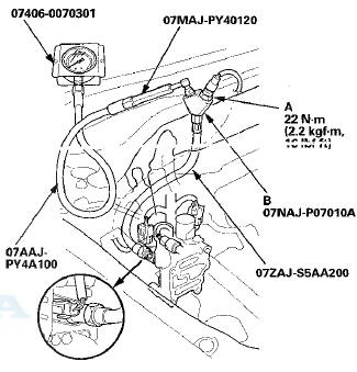
DTC P2646:
Rocker Arm Oil Pressure Switch Circuit Low Voltage (All models except PZEV)
Special Tools Required
- Pressure Gauge Adapter 07NAJ-P07010A
- A/T Low Pressure Gauge W/Panel 07406-0070301
- AT Pressure Test Hose 07AAJ-PY4A100
- A/T Pressure Adapter 07MAJ-PY40120
- Oil Pressure Hose 07ZAJ-S5AA200
NOTE: - Before you troubleshoot record all freeze data and any on-board snapshot and review the general troubleshooting information (see page 11-3).
- If DTC P2648 and/or P2649 are stored at the same time as DTC P2646, troubleshoot those DTCs first then recheck for DTC P2646.
1. Check the engine oil level.
Is the level OK? YES-Go to step 2.
NO-Adjust the engine oil to the proper level, then go to step 20.
2. Turn the ignition switch to ON (II).
3. Clear the DTC with the HDS.
4. Do the VTEC TEST in the INSPECTION MENU with the HDS.
Is the result OK?
YES
-lntermittent failure, the system is OK at this time.
Check for poor connections or loose terminals at the rocker arm oil pressure switch, the rocker arm oil control solenoid, and the ECM/PCM.
NO
-Go to step 5.
5. Turn the ignition switch to LOCK (0).
6. Disconnect the rocker arm oil pressure switch 2P connector.
7. Turn the ignition switch to ON (II).
8. Check the VTEC PRES SW in the DATA LIST with the HDS.
Is SWITCH ON indicated?
YES
-Go to step 15.
NO
-Go to step 9.
9. Turn the ignition switch to LOCK (0).
10. Remove the rocker arm oil pressure switch (A), and attach the special tools as shown, then attach the rocker arm oil pressure switch to the oil pressure gauge adapter (B).
11. Reconnect the rocker arm oil pressure switch 2P connector.
12. Start the engine.
13. Do the VTEC TEST in the INSPECTION MENU with the HDS.
14. Check the oil pressure.
Does the oil pressure increase to at least 392 kPa (4.0 kgf/cm2, 56.9 psi)? YES-Replace the rocker arm oil pressure switch (see page 11-276), then go to step 19.
NO-lnspect the VTEC system. If it is OK, replace the rocker arm oil control valve (see page 11-274), then go to step 19.
15. Turn the ignition switch to LOCK (0).
16. Jump the SCS line with the HDS.
17. Disconnect ECM/PCM connector C (49P).
18. Check for continuity between ECM/PCM connector terminal C22 and body ground.
ECM/PCM CONNECTOR C (49P)
Terminal side of female terminals
Is there continuity? YES-
Repair short in the wire between the ECM/PCM (C22) and the rocker arm oil pressure switch, then go to step 19.
NO
-Go to step 25.
19. Reconnect all connectors.
20. Turn the ignition switch to ON (II).
21. Reset the ECM/PCM with the HDS.
22. Do the ECM/PCM idle learn procedure (see page 11-293).
23. Do the VTEC TEST in the INSPECTION MENU with the HDS.
24. Check for Pending or Confirmed DTCs with the HDS.
Is DTC P2646 indicated? YES
-Check for poor connections or loose terminals at the rocker arm oil pressure switch, the rocker arm oil control solenoid and the ECM/PCM, then go step 1.
NO
-Troubleshooting is complete. If any other Pending or Confirmed DTCs are indicated, go to the indicated DTCs troubleshooting.
25. Reconnect all connectors.
26. Update the ECM/PCM if it does not have the latest software (see page 11 -203), or substitute a known-good ECM/PCM (see page 11-7).
27. Do the VTEC TEST in the INSPECTION MENU with the HDS.
28. Check for Pending or Confirmed DTCs with the HDS.
Is DTC P2646 indicated? YES
-Check for poor connections or loose terminals at the rocker arm oil pressure switch, the rocker arm oil control solenoid and the ECM/PCM. If the ECM/PCM was updated, substitute a known-good ECM/PCM (see page 11-7), then go to step 27. If the ECM/PCM was substituted, go to step 1.
NO
-lf the ECM/PCM was updated, troubleshooting is complete. If the ECM/PCM was substituted, replace the original ECM/PCM (see page 11-204). If any other Pending or Confirmed DTCs are indicated, go to the indicated DTCs troubleshooting.
DTC P2646:
Rocker Arm Oil Pressure Switch A Circuit Low Voltage (PZEV model)
DTC P2647:
Rocker Arm Oil Pressure Switch A Circuit High Voltage (PZEV model)
Special Tools Required
-
Pressure Gauge Adapter 07NAJ-P07010A
-
A/T Low Pressure Gauge W/Panel 07406-0070301
-
AT Pressure Test Hose 07AAJ-PY4A100
-
A/T Pressure Adapter 07MAJ-PY40120
-
Oil Pressure Hose 07ZAJ-S5AA200
NOTE: - Before you troubleshoot, record all freeze data and any on-board snapshot, and review the general troubleshooting information (see page 11-3).
- If DTC P2648 and/or P2649 are stored at the same time as DTC P2646 and/or P2647, troubleshoot those DTCs first, then recheck for DTC P2646 and/or P2647.
1. Check the engine oil level.
Is the level OK? YES-Go to step 2.
NO-Adjust the engine oil level to the proper level, then go to step 29.
2. Turn the ignition switch to ON (II).
3. Clear the DTC with the HDS.
4. Select the VTEC TEST in the INSPECTION MENU with the HDS, and do the VTEC TEST.
Are VTECIN-0 and VTECEX-0 indicated? YES
-lntermittent failure, the system is OK at this time.
Check for poor connections or loose terminals at rocker arm oil pressure switch A, rocker arm oil control solenoid A, and the PCM.
NO-
lf the result is - VTECIN-1:Go to step 5.
- VTECIN-3: Go to step 14.
- VTECIN-3 and VTECEX-3 indicated at the same time: Check the oil passage between the engine oil pressure switch and the rocker arm oil control valve filter. If it is OK, go to step 14.
- VTECIN-2, VTECIN-4: Inspect the intake valve side of the VTEC system. If it is OK, replace the rocker arm oil control valve (see page 11-275), then go to step 29.
- VTECEX-1, 2, 3,4: The exhaust valve side VTEC system is faulty. Go to the troubleshooting for P2651/P2652 (see page 11-265).
5. Turn the ignition switch to LOCK (0).
6. Disconnect the rocker arm oil pressure switch A 2P connector.
7. At rocker arm oil pressure switch A side, check for continuity between its 2P connector terminals.
ROCKER ARM OIL PRESSURE SWITCH A 2P CONNECTOR
Terminal side of male terminals
Is there continuity? YES
-Go to step 8.
NO
-Replace rocker arm oil pressure switch A (see page 11-276), then go to step 29.
8. Turn the ignition switch to ON (II).
9. Measure the voltage between rocker arm oil pressure switch A 2P connector terminal No. 1 and body ground.
ROCKER ARM OIL PRESSURE SWITCH A 2P CONNECTOR
Wire side of female terminals
Is there battery voltage? YES
-Repair open in the wire between rocker arm oil pressure switch A and G101 (see page 22-22), then go to step 28.
NO-
Go to step 10.
10. Turn the ignition switch to LOCK (0).
11. Jump the SCS line with the HDS.
12. Disconnect PCM connector C (49P).
13. Check for continuity between rocker arm oil pressure switch A 2P connector terminal No. 1 and PCM connector terminal C22.
ROCKER ARM OIL PRESSURE SWITCH A 2P CONNECTOR
Terminal side of female terminals
Is there continuity? YES
-Check for poor connections or loose terminals at rocker arm oil pressure switch A, rocker arm oil control solenoid A, and the PCM. If the connections and terminals are OK, go to step 35.
NO
-Repair open in the wire between rocker arm oil pressure switch A and the PCM (C22), then go to step 29.
14. Turn the ignition switch to LOCK (0).
15. Disconnect the rocker arm oil pressure switch A 2P connector.
-16. Turn the ignition switch to ON (II).
17. Check ROCKER ARM OIL PRESSURE SWITCH A in the DATA LIST with the HDS.
Is SWITCH ON indicated? YES-Go to step 24.
NO
-Go to step 18.
18. Turn the ignition switch to LOCK (0).
19. Remove rocker arm oil pressure switch A (see page 11-276), then reinstall the rocker arm oil control valve and its filter (see page 11-275) without installing rocker arm oil pressure switch A.
20. Attach the special tools to the rocker arm oil control valve as shown, then attach rocker arm oil pressure switch A to the oil pressure gauge adapter (B).
21. Reconnect the rocker arm oil pressure switch A 2P connector.
22. Select the VTEC TEST in the INSPECTION MENU with the HDS, and do the VTEC TEST.
23. Check the oil pressure during the High V/T/LIFT (TEST STATUS 4).
Does the oil pressure increase to at least 191 kPa (2.0 kgf/cm2, 27.7 psi)? YES
-Replace rocker arm oil pressure switch A (see page 11-276), then go to step 29.
NO
-lnspect the intake valve side of the VTEC system.
If it is OK, replace the rocker arm oil control valve (see page 11-275), then go to step 29.
24. Turn the ignition switch to LOCK (0).
25. Jump the SCS line with the HDS.
26. Disconnect PCM connector C (49P).
27. Check for continuity between PCM connector terminal C22 and body ground.
PCM CONNECTOR C (49P)
Terminal side of female terminals
Is there continuity? YES
-Repair short in the wire between the PCM (C22) and rocker arm oil pressure switch A, then go to step 29.
NO
-Check for poor connections or loose terminals at rocker arm oil pressure switch A, rocker arm oil control solenoid A, and the PCM. If the connectors and the terminals are OK, go to step 35.
28. Turn the ignition switch to LOCK (0).
29. Reconnect all connectors.
30. Turn the ignition switch to ON (II).
31. Reset the PCM with the HDS.
32. Do the PCM idle learn procedure (see page 11-293).
33. Select the VTEC TEST in the INSPECTION MENU with the HDS, and do the VTEC TEST.
Are VTECIN-0 and VTECEX-0 indicated? YES
-Go to step 34.
NO
-Check for poor connections or loose terminals at rocker arm oil pressure switch A, rocker arm oil control solenoid A, and the PCM, then go to step 1.
34. Check for Pending or Confirmed DTCs with the HDS.
Are any Pending or Confirmed DTCs indicated? YES
-lf any other Pending or Confirmed DTCs are indicated, go to the indicated DTCs troubleshooting.
NO
-Troubleshooting is complete.
35. Reconnect all connectors.
36. Update the PCM if it does not have the latest software (see page 11-203), or substitute a known-good PCM (see page 11-7).
37. Select the VTEC TEST in the INSPECTION MENU with the HDS, and do the VTEC TEST.
Are VTECIN-0 and VTECEX-0 indicated? YES-
Go to step 38.
NO
-lf the PCM was updated, substitute a known-good PCM (see page 11-7), then recheck. If the PCM was substituted, go to step 1.
38. Check for Pending or Confirmed DTCs with the HDS.
Are any Pending or Confirmed DTCs indicated? YES
-lf any other Pending or Confirmed DTCs are indicated, go to the indicated DTCs troubleshooting.
NO-lf the PCM was updated, troubleshooting is
complete. If the PCM was substituted, replace the original PCM (see page 11-204).
DTC P2647:
Rocker Arm Oil Pressure Switch Circuit High Voltage (All models except PZEV)
NOTE: - Before you troubleshoot record all freeze data and any on-board snapshot and review the general troubleshooting information (see page 11-3).
- If DTC P2648 and/or P2649 are stored at the same time as DTC P2647, troubleshoot those DTCs first, then recheck for DTC P2647.
1. Check the engine oil level.
Is the level OK? YES
-Go to step 2.
NO-
Adjust the engine oil to the proper level, then go 2. Turn the ignition switch to ON (II).
3. Clear the DTC with the HDS.
4. Do the VTEC TEST in the INSPECTION MENU with the HDS.
NOTE: if DTC stored during VTEC TEST, check for DTCs MENU. If DTC P2647 indicated, go to step 6. If any other Pending or Confirmed DTCs are indicated, go to the indicated DTCs troubleshooting.
Is the result OK? YES
-lntermittent failure, the system is OK at this time.
Check for poor connections or loose terminals at the rocker arm oil pressure switch, the rocker arm oil control solenoid, and the ECM/PCM.- NO
-Go to step 5.
5. Check the result of step 4.
- VTEC Switch Failure
- VTEC Switch Open
- VTEC Switch SIG Line Open
- VTEC Switch GND Line Open
Is the test result any of those above? YES
-Go to step 6.
NO
-Check for poor connections or loose terminals at the rocker arm oil pressure switch. If it is OK, replace the rocker arm oil control valve (see page 11-274), then, go to step 15.
6. Turn the ignition switch to LOCK (0).
7. Disconnect the rocker arm oil pressure switch 2P connector.
8. At the rocker arm oil pressure switch side, check for continuity between its 2P connector terminals.
ROCKER ARM OIL PRESSURE SWITCH A 2P CONNECTOR
Terminal side of male terminals
Is there continuity? YES-Go to step 9.
NO-Replace the rocker arm oil pressure switch (see page 11-276), then go to step 16.
9. Turn the ignition switch to ON (II).
10. Measure the voltage between rocker arm oil pressure switch 2P connector terminal No. 1 and body ground.
ROCKER ARM OIL PRESSURE SWITCH A 2P CONNECTOR
Wire side of female terminals
Is there battery voltage? YES
-Repair open in the wire between the rocker arm oil pressure switch and G101; M/T (see page 22-20), A/T (see page 22-22), then go to step 15.
NO
-Go to step 11.
11. Turn the ignition switch to LOCK (0).
12. Jump the SCS line with the HDS.
13. Disconnect ECM/PCM connector C (49P).
14. Check for continuity between rocker arm oil pressure switch 2P connector terminal No. 1 and ECM/PCM connector terminal C22.
ROCKER ABM OIL PRESSURE SWITCH 2P CONNECTOR
Terminal side of female terminals
Is there continuity? YES
-Go to step 21.
NO
-Repair open in the wire between the ECM/PCM (C22) and the rocker arm oil pressure switch, then go to step 16.
15. Turn the ignition switch to LOCK (0).
16. Reconnect all connectors.
17. Turn the ignition switch to ON (II).
18. Reset the ECM/PCM with the HDS.
19. Do the ECM/PCM idle learn procedure (see page 11-293).
20. Check for Pending or Confirmed DTCs with the HDS.
Is DTC P2647 indicated? YES-
Check for poor connections or loose terminals at the rocker arm oil pressure switch, the rocker arm oil control solenoid, and the ECM/PCM, then go to step 1.
NO
-Troubleshooting is complete. If any other Pending or Confirmed DTCs were indicated, go to the indicated DTCs troubleshooting.
21. Reconnect all connectors.
22. Update the ECM/PCM if it does not have the latest software (see page 11 -203), or substitute a known-good ECM/PCM (see page 11-7).
23. Start the engine, and let it idle.
24. Check for Pending or Confirmed DTCs with the HDS.
Is DTC P2647 indicated? YES
-Check for poor connections or loose terminals at the rocker arm oil pressure switch, the rocker arm oil control solenoid, and the ECM/PCM. If the ECM/PCM was updated, substitute a known-good ECM/PCM (see page 11-7), then go to step 23. If the ECM/PCM was substituted, go to step 1.
NO
-lf the ECM/PCM was updated, troubleshooting is complete. If the ECM/PCM was substituted, replace the original ECM/PCM (see page 11-204). If any other Pending or Confirmed DTCs were indicated, go to the indicated DTCs troubleshooting.
DTC P2648:
Rocker Arm Oil Control Solenoid Circuit Low Voltage (All models except PZEV)
NOTE: Before you troubleshoot record all freeze data and any on-board snapshot, and review the general troubleshooting information (see page 11-3).
1. Turn the ignition switch to ON (II).
2. Clear the DTC with the HDS.
3. Do the VTEC TEST in the INSPECTION MENU with the HDS.
Is the result OK? YES
-lntermittent failure, the system is OK at this time.
Check for poor connections or loose terminals at the rocker arm oil control solenoid and the ECM/PCM.- NO
-Go to step 4.
4. Turn the ignition switch to LOCK (0).
5. Disconnect the rocker arm oil control solenoid 2P connector.
6. Measure the resistance between rocker arm oil control solenoid 2P connector terminals No. 1 and No. 2.
ROCKER ARM OIL CONTROL SOLENOID 2P CONNECTOR

Terminal side of male terminals
Is there 14-”30 O at room temperature? YES
-Go to step 7.
NO-
Go to step 10.
7. Jump the SCS line with the HDS.
8. Disconnect ECM/PCM connector B (49P).
9. Check for continuity between ECM/PCM connector terminal B35 and body ground.
ECM/PCM CONNECTOR B (49P)
Is there continuity? YES
-Repair short in the wire between the ECM/PCM (B35) and the rocker arm oil control solenoid, then go to step 11.
NO
-Go to step 18.
10. Replace the rocker arm oil control valve (see page 11-274).
11. Reconnect all connectors.
12. Turn the ignition switch to ON (II).
13. Reset the ECM/PCM with the HDS.
14. Do the ECM/PCM idle learn procedure (see page 11-293).
15. Do the VTEC TEST in the INSPECTION MENU with the HDS.
16. Check for Pending or Confirmed DTCs with the HDS.
Is DTC P2648 indicated? YES
-Check for poor connections or loose terminals at the rocker arm oil control solenoid and the ECM/PCM, then go to step 1.
NO
-Go to step 17.
17. Monitor the OBD STATUS for DTC P2648 in the DTCs MENU with the HDS.
Does the screen indicate PASSED? YES
-Troubleshooting is complete. If any other Pending or Confirmed DTCs were indicated in step 16, go to the indicated DTCs troubleshooting.
NO
-lf the screen indicates FAILED, check for poor connections or loose terminals at the rocker arm oil control solenoid and the ECM/PCM, then go to step 1.
If the screen indicates NOT COMPLETED, go to step 15.
18. Reconnect all connectors.
19. Update the ECM/PCM if it does not have the latest software (see page 11-203), or substitute a known-good ECM/PCM (see page 11-7).
20. Do the VTEC TEST in the INSPECTION MENU with the HDS.
21. Check for Pending or Confirmed DTCs with the HDS.
Is DTC P2648 indicated? YES
-Check for poor connections or loose terminals at the rocker arm oil control solenoid and the ECM/PCM.
If the ECM/PCM was updated, substitute a known-good ECM/PCM (see page 11 -7), then go to step 20. If the ECM/PCM was substituted, go to step 1.
NO
-Go to step 22.
22. Monitor the OBD STATUS for DTC P2648 in the DTCs MENU with the HDS.
Does the screen indicate PASSED? YES
-lf the ECM/PCM was updated, troubleshooting is complete. If the ECM/PCM was substituted, replace the original ECM/PCM (see page 11-204). If any other Pending or Confirmed DTCs were indicated in step 21, go to the indicated DTCs troubleshooting.
NO
-lf the screen indicates FAILED, check for poor connections or loose terminals at the rocker arm oil control solenoid and the ECM/PCM. If the ECM/PCM was updated, substitute a known-good ECM/PCM (see page 11-7), then go to step 20. If the ECM/PCM was substituted, go to step 1. If the screen indicates NOT COMPLETED, go to step 20.
DTC P2848:
Rocker Arm Oil Control Solenoid A (Intake Valve Side) Circuit Low Voltage (PZEV model)
NOTE: Before you troubleshoot, record all freeze data and any on-board snapshot, and review the general troubleshooting information (see page 11-3).
1. Turn the ignition switch to ON (II).
2. Clear the DTC with the HDS.
3. Select the VTEC TEST in the INSPECTION MENU with the HDS, and do the Solenoid Valve ACTIVATION of the ROCKER ARM SOLENOID A.
4. Check for Pending or Confirmed DTCs with the HDS.
Is DTC P2648 indicated? YES
-Go to step 5.
NO
-lntermittent failure, the system is OK at this time.
Check for poor connections or loose terminals at rocker arm oil control solenoid A and the PCM.H 5. Turn the ignition switch to LOCK (0).
6. Disconnect the rocker arm oil control solenoid A 2P connector.
7. Measure the resistance between rocker arm oil control solenoid A 2P connector terminals No. 1 and No. 2.
ROCKER ARM OIL CONTROL SOLENOID A 2P CONNECTOR
 Terminal side of male terminals
Is there 14-”30 Q at room temperature? YES
-Go to step 8.
NO
-Go to step 11.
8. Jump the SCS line with the HDS.
9. Disconnect PCM connector B (49P).
10. Check for continuity between PCM connector terminal B35 and body ground.
PCM CONNECTOR B (49P)
Terminal side of female terminals
Is there continuity? YES
-Repair short in the wire between the PCM (B35) and rocker arm oil control solenoid A, then go to step 12.
NO
-Check for poor connections or loose terminals at the PCM and rocker arm oil control solenoid A, then go to step 19.
11. Replace the rocker arm oil control valve (see page 11-275).
12. Reconnect all connectors.
13. Turn the ignition switch to ON (II).
14. Reset the PCM with the HDS.
15. Do the PCM idle learn procedure (see page 11-293).
16. Select the VTEC TEST in the INSPECTION MENU with the HDS, and do the Solenoid Valve ACTIVATION of the ROCKER ARM SOLENOID A.
17. Check for Pending or Confirmed DTCs with the HDS.
Is DTC P2648 indicated? YES
-Check for poor connections or loose terminals at rocker arm oil control solenoid A and the PCM, then go to step 1.
NO
-Go to step 18.
18. Monitor the OBD STATUS for DTC P2648 in the DTCs MENU with the HDS.
Does the screen indicate PASSED? YES
-Troubleshooting is complete. If any other Pending or Confirmed DTCs were indicated in step 17, go to the indicated DTCs troubleshooting.- NO
-lf the screen indicates FAILED, go to step 1 and recheck. If the screen indicates NOT COMPLETED, go to step 16.
19. Reconnect all connectors.
20. Update the PCM if it does not have the latest software (see page 11-203), or substitute a known-good PCM (see page 11-7).
21. Select the VTEO TEST in the INOPECTION MENU with the HDS, and do the Solenoid Valve ACTIVATION of the ROCKER ARM SOLENOID A.
22. Check for Pending or Confirmed DTCs with the HDS.
Is DTC P2648 indicated? YES
-Check for poor connections or loose terminals at rocker arm oil control solenoid A and the PCM. If the PCM was updated, substitute a known-good PCM (see page 11 -7), then go to step 21. If the PCM was substituted, go to step 1.
NO
-Go to step 23.
23. Monitor the OBD STATUS for DTC P2648 in the DTCs MENU with the HDS.
Does the screen indicate PASSED? YES-
lf the PCM was updated, troubleshooting is complete. If the PCM was substituted, replace the original PCM (see page 11-204). If any other Pending or Confirmed DTCs were indicated in step 22, go to the indicated DTCs troubleshooting.
NO
-lf the screen indicates FAILED, check for poor connections or loose terminals at rocker arm oil control solenoid A and the PCM. If the PCM was updated, substitute a known-good PCM (see page 11-7), then go to step 21. If the PCM was substituted, go to step 1. If the screen indicates NOT COMPLETED, go to step 21.
DTC P2649:
Rocker Arm Oil Control Solenoid Circuit High Voltage (All models except PZEV)
NOTE: Before you troubleshoot record all freeze data and any on-board snapshot and review the general troubleshooting information (see page 11-3).
1. Turn the ignition switch to ON (II).
2. Clear the DTC with the HDS.
3. Start the engine. Hold the engine speed at 3,000 rpm without load (A/T in P or N, M/T in neutral) until the radiator fan comes on, then let it idle.
4. Check for Pending or Confirmed DTCs with the HDS.
Is DTC P2649 Indicated? YES
-Go to step 5.
NO
-lntermittent failure, the system is OK at this time.
Check for poor connections or loose terminals at the rocker arm oil control solenoid and the ECM/PCM.- 5. Turn the ignition switch to LOCK (0).
6. Disconnect the rocker arm oil control solenoid 2P connector.
7. Measure the resistance between rocker arm oil control solenoid 2P connector terminals No. 1 and No. 2.
ROCKER ARM OIL CONTROL SOLENOID 2P CONNECTOR

Terminal side of male terminals
Is there 14-”30 D at room temperature? YES
-Go to step 8.
NO
-Go to step 12.
8. Check for continuity between rocker arm oil control solenoid 2P connector terminal No. 1 and body ground.
ROCKER ARM OIL CONTROL SOLENOID 2P CONNECTOR
Wire side of female terminals
Is there continuity? YES-
Go to step 9.
NO-
Repair open in the wire between the rocker arm oil control solenoid and G101; M/T (see page 22-20), A/T (see page 22-22), then go to step 13.
9. Jump the SCS line with the HDS.
10. Disconnect ECM/PCM connector B (49P).
11. Check for continuity between ECM/PCM connector terminal B35 and rocker arm oil control solenoid 2P connector terminal No. 2.
ROCKER ARM OIL CONTROL SOLENOID 2P CONNECTOR
Terminal side of female terminals
Is there continuity? YES
-Go to step 19.
NO
-Repair open in the wire between the ECM/PCM (B35) and the rocker arm oil control solenoid, then go to step 13.
12. Replace the rocker arm oil control valve (see page 11-274).
13. Reconnect all connectors.
14. Turn the ignition switch to ON (II).
15. Reset the ECM/PCM with the HDS.
16. Do the ECM/PCM idle learn procedure (see page 11-293).
17. Check for Pending or Confirmed DTCs with the HDS.
Is DTC P2649 indicated? YES
-Check for poor connections or loose terminals at the rocker arm oil control solenoid and the ECM/PCM, then go to step 1.
NO
-Go to step 18.
18. Monitor the OBD STATUS for DTC P2649 in the DTCs MENU with the HDS.
Does the screen indicate PASSED? YES
-Troubleshooting is complete. If any other Pending or Confirmed DTCs were indicated in step 17, go to the indicated DTCs troubleshooting.
NO
-lf the screen indicates FAILED, check for poor connections or loose terminals at the rocker arm oil control solenoid and the ECM/PCM, then go to step 1.
If the screen indicates NOT COMPLETED, keep idling until a result comes on.
19. Reconnect all connectors.
20. Update the ECM/PCM if it does not have the latest software (see page 11-203), or substitute a known-good ECM/PCM (see page 11-7).
21. Start the engine, and let it idle.
22. Check for Pending or Confirmed DTCs with the HDS.
Is DTC P2649 indicated? YES
-Check for poor connections or loose terminals at the rocker arm oil control solenoid and the ECM/PCM.
If the ECM/PCM was updated, substitute a known-good ECM/PCM (see page 11-7), then recheck.
If the ECM/PCM was substituted, go to step 1.
NO
-Go to step 23.
23. Monitor the OBD STATUS for DTC P2649 in the DTCs MENU with the HDS.
Does the screen indicate PASSED? YES
-lf the ECM/PCM was updated troubleshooting is complete. If the ECM/PCM was substituted, replace the original ECM/PCM (see page 11-204). If any other Pending or Confirmed DTCs were indicated in step 22, go to the indicated DTCs troubleshooting.
NO
-lf the screen indicates FAILED, check for poor connections or loose terminals at the rocker arm oil control solenoid and the ECM/PCM. If the ECM/PCM was updated, substitute a known-good ECM/PCM (see page 11-7), then recheck. If the ECM/PCM was substituted, go to step 1. If the screen indicates NOT COMPLETED, keep idling until a result comes on.
DTC P2649:
Rocker Arm Oil Control Solenoid A (Intake Valve Side) Circuit High Voltage (PZEV model)
NOTE: Before you troubleshoot, record all freeze data and any on-board snapshot, and review the general troubleshooting information (see page 11-3).
1. Turn the ignition switch to ON (II).
2. Clear the DTC with the HDS.
3. Start the engine. Hold the engine speed at 3,000 rpm without load (in P or N) until the radiator fan comes on, then let it idle.
4. Check for Temporary DTCs or DTCs with the HDS.
Is DTC P2649 Indicated? YES
-Go to step 5.
NO
-lntermittent failure, the system is OK at this time.
Check for poor connections or loose terminals at rocker arm oil control solenoid A and the PCM.H 5. Turn the ignition switch to LOCK (0).
6. Disconnect the rocker arm oil control solenoid A 2P connector.
7. Measure the resistance between rocker arm oil control solenoid A 2P connector terminals No. 1 and No. 2.
ROCKER ARM OIL CONTROL SOLENOID A 2P CONNECTOR
Terminal side of male terminals
Is there 14-”30 Q at room temperature? YES
-Go to step 8.
NO-
Go to step 12.
8. Check for continuity between rocker arm oil control solenoid A 2P connector terminal No. 1 and body ground.
ROCKER ARM OIL CONTROL SOLENOID A zr CONNECTOR
Wire side of female terminals
Is there continuity? YES-
Go to step 9. NO-
Repair open in the wire between the rocker arm oil control solenoid A and G101 (see page 22-22), then goto step 13.
9. Jump the SCS line with the HDS.
10. Disconnect PCM connector B (49P).
11. Check for continuity between PCM connector terminal B35 and rocker arm oil control solenoid A 2P connector terminal No. 2.
ROCKER ARM OIL CONTROL SOLENOID A 2P CONNECTOR

Terminal side of female terminals
Is there continuity? YES
-Go to step 19.
NO
-Repair open in the wire between the PCM (B35) and the rocker arm oil control solenoid A, then go to step 13.
12. Replace the rocker arm oil control valve {see page 11-275).
13. Reconnect ail connectors.
14. Turn the ignition switch to ON (II).
15. Reset the PCM with the HDS.
16. Do the PCM idle learn procedure (see page 11-293).
17. Check for Pending or Confirmed DTCs with the HDS.
Is DTC P2649 indicated? YES
-Check for poor connections or loose terminals at rocker arm oil control solenoid A and the PCM, then go to step 1.
NO
-Go to step 18.
18. Monitor the OBD STATUS for DTC P2649 in the DTCs MENU with the HDS.
Does the screen indicate PASSED? YES
-Troubleshooting is complete. If any other Pending or Confirmed DTCs were indicated in step 17, go to the indicated DTCs troubleshooting.- NO
-lf the screen indicates FAILED, go to step 1 and recheck. If the screen indicates NOT COMPLETED, keep idling until a result comes on.
19. Reconnect all connectors.
20. Update the PCM if it does not have the latest software (see page 11-203), or substitute a known-good PCM (see page 11-7).
21. Start the engine, and let it idle.
22. Check for Pending or Confirmed DTCs with the HDS.
Is DTC P2649 indicated? YES
-Check for poor connections or loose terminals at rocker arm oil control solenoid A and the PCM. If the PCM was updated, substitute a known-good PCM (see page 11-7), then recheck. If the PCM was substituted, go to step 1.
NO-
Go to step 23.
23. Monitor the OBD STATUS for DTC P2649 in the DTCs MENU with the HDS.
Does the screen indicate PASSED? YES
-lf the PCM was updated, troubleshooting is complete. If the PCM was substituted, replace the original PCM (see page 11-204). If any other Pending or Confirmed DTCs were indicated in step 22, go to the indicated DTCs troubleshooting.
NO
-lf the screen indicates FAILED, check for poor connections or loose terminals at rocker arm oil control solenoid A and the PCM. If the PCM was updated, substitute a known-good PCM, then recheck.
If the PCM was substituted, go to step 1. If the screen indicates NOT COMPLETED, keep idling until a result comes on.
DTC P2651
: Rocker Arm Oil Pressure Switch B Circuit Low Voltage (PZEV model)
DTC P2652:
Rocker Arm Oil Pressure Switch B Circuit High Voltage (PZEV model)
Special Tools Required
Pressure Gauge Adapter 07NAJ-P07010A
A/T Low Pressure Gauge W/Panel 07406-0070301
AT Pressure Test Hose 07AAJ-PY4A100
A/T Pressure Adapter 07MAJ-PY40120
Oil Pressure Hose 07ZAJ-S5AA200
NOTE: m Before you troubleshoot, record all freeze data and any on-board snapshot, and review the general troubleshooting information (see page 11-3).
- If DTC P2653 and/or P2654 are stored at the same time as DTC P2651 and/or P2652, troubleshoot those DTCs first, then recheck for DTC P2651 and/or P2652.
1. Check the engine oil level.
Is the level OK? YES
-Go to step 2.
NO
-Adjust the engine oil level to the proper level, then go to step 29.
2. Turn the ignition switch to ON (II).
3. Clear the DTC with the HDS.
4. Select the VTEC TEST in the INSPECTION MENU with the HDS, and do the VTEC TEST.
Are VTECEX-0 and VTECIN-0 Indicated? YES
-Intermittent faiIure, the system is OK at this time.
Check for poor connections or loose terminals at rocker arm oil pressure switch B, and rocker arm oil control solenoid B, and the PCM.
NO-
lf the result is
- VTECEX-1: Go to step 5.
- VTECEX-3: Go to step 14.
m VTECEX-3 and VTECIN-3 indicated at the same time: Check the oil passage between the engine oil pressure switch and the rocker arm oil control valve filter. If it is OK, go to step 14.
- VTECEX-2, VTECEX-4: Inspect the exhaust side of the VTEC system. If it is OK, replace the rocker arm oil control valve (see page 11-275), then go to step 29.
- VTECIN-1,2,3,4: The intake valve side VTEC system is faulty. Go to the troubleshooting for P2646/ P2647 (see page 11-253).
5. Turn the ignition switch to LOCK (0).
6. Disconnect the rocker arm oil pressure switch B 2P connector.
7. At the rocker arm oil pressure switch B side, check for continuity between its 2P connector terminals.
ROCKER ARM OIL PRESSURE SWITCH B 2P CONNECTOR
Terminal side of male terminals
Is there continuity? YES-
Go to step 8.
NO-
Replace rocker arm oil pressure switch B (see page 11-277), then go to step 29.
8. Turn the ignition switch to ON (II).
9. Measure the voltage between rocker arm oil pressure switch B 2P connector terminal No. 1 and body ground.
ROCKER ARM OIL PRESSURE SWITCH B 2P CONNECTOR
Wire side of female terminals
Is there battery voltage? YES
-Repair open in the wire between rocker arm oil pressure switch B and G101 (see page 22-22), then go to step 28.
NO
-Go to step 10.
10. Turn the ignition switch to LOCK (0).
11. Jump the SCS line with the HDS.
12. Disconnect PCM connector B (49P).
13. Check for continuity between rocker arm oil pressure switch B 2P connector terminal No. 1 and PCM connector terminal B43.
ROCKER ARM OIL PRESSURE SWITCH B 2P CONNECTOR
Terminal side of female terminals
Is there continuity? YES
-Check for poor connections or loose terminals at rocker arm oil pressure switch B, rocker arm oil control solenoid B, and the PCM. If the connections and terminals are OK, go to step 35.
NO
-Repair open in the wire between rocker arm oil pressure switch B and the PCM (B43), then go to step 29.
14. Turn the ignition switch to LOCK (0).
15. Disconnect the rocker arm oil pressure switch B 2P connector.
16. Turn the ignition switch to ON (II).
17. Check the ROCKER ARM OIL PRESSURE SWITCH B in the DATA LIST with the HDS.
Is SWITCH ON indicated? YES
-Go to step 24.
NO
-Go to step 18.
18. Turn the ignition switch to LOCK (0).
19. Remove rocker arm oil pressure switch B (see page 11-277), then reinstall the rocker arm oil control valve and its filter (see page 11-275) without installing rocker arm oil pressure switch B.
20. Attach the special tools to the rocker arm oil control valve as shown, then attach rocker arm oil pressure switch B to the oil pressure gauge adapter (A).
21. Reconnect the rocker arm oil pressure switch B 2P connector.
22. Select the VTEC TEST in the INSPECTION MENU with the HDS, and do the VTEC TEST.
23. Check the oil pressure during the Low V/T/LIFT and the High V/T/LIFT (TEST STATUS 3 and 4).
Does the oil pressure increase to at least 191 kPa (2.0 kgf/cm % 27.7 psi)? YES-
Replace rocker arm oil pressure switch B (see page 11 -277), then go to step 29.
NO-
lnspect the VTEC system. If it is OK, replace the rocker arm oil control valve (see page 11-275), then go to step 29.
24. Turn the ignition switch to LOCK (0).
25. Jump the SCS line with the HDS.
26. Disconnect PCM connector B (49P).
27. Check for continuity between PCM connector terminal B43 and body ground.
PCM CONNECTOR B (4SP)
Terminal side of female terminals
Is there continuity? YES
-Repair short in the wire between the PCM (B43) and rocker arm oil pressure switch B, then go to step 29.
NO
-Check for poor connections or loose terminals at rocker arm oil pressure switch B, rocker arm oil control solenoid B, and the PCM. If the connections and the terminals are OK, go to step 35.
28. Turn the ignition switch to LOCK (0).
29. Reconnect all connectors.
30. Turn the ignition switch to ON (II).
31. Reset the PCM with the HDS.
32. Do the PCM idle learn procedure (see page 11-293).
33. Select the VTEC TEST in the INSPECTION MENU with the HDS, and do the VTEC TEST.
Are
 Component Location I n d e x
All models except PZEV
...
 VTC Oil Control Solenoid Valve
Removal/Test/lnstallation
VTC Oil Control Solenoid Valve
Removal/Test/lnstallation
1 Disconnect the VTC oil control solenoid valve 2P
connector (A).
2. Remove the bolt (B) and the VTC oil control solenoid
valve (C).
3. Connect VTC oil control valve 2P connector terminal
No. ...
See also:
Secondary Shaft 1 st Gear Axial
Clearance Inspection
Special Tools Required
Attachment, 42 mm I.D. 07QAD-P0A0100
1. Remove the secondary shaft transmission housing
bearing (see page 14-270).
2. Install the thrust needle b e a r i n g (A), the need ...
Bearing Removal
Special Tools Required
•Attachment, 78x80 mm 07NAD-PX40100
-Driver Handle, 15 x 135L 07749-0010000
-Bearing Driver Attachment, 42 x 47 07746-0010300
1. Remove the idler gear shaft (see page 1 ...
A/C Condenser Fan High Speed Circuit
Troubleshooting
ECM/PCM CONNECTOR A (49P)
Terminal side of female terminals
Is there battery voltage?
YES-Go to step 6.
NO-Repair an open in the wire between the
under-hood fuse/relay box and the ECM/PCM. If ...