 Honda Accord: Cylinder Head Cover Installation
1. Thoroughly clean the head cover gasket and the groove.
2. Install the head cover gasket (A) in the groove of the cylinder head cover (B).
3. Check that the mating surfaces are clean and dry.
4. Apply liquid gasket, P/N 08717-0004, 08718-0003, or 08718-0009, on the chain case and the No. 5 rocker shaft holder mating areas (A). Install the component within 5 minutes of applying the liquid gasket.
NOTE: If too much time has passed after applying the liquid gasket, remove the old liquid gasket and residue, then reapply new liquid gasket.
5. Set the spark plug seals (A) on the spark plug tubes.
Place the cylinder head cover (B) on the cylinder head, then slide the cover slightly back and forth to seat the head cover gasket.
6. Inspect the cover washers (C). Replace any washer that is damaged or deteriorated.
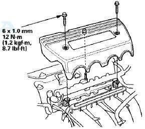
7. Tighten the bolts in three steps. In the final step torque all bolts, in sequence, to 12 N-m (1.2 kgf-m, 8.7 Ibfft).
NOTE: - Wait at least 30 minutes before filling the engine with oil.
- Do not run the engine for at least 3 hours after installing the head cover.
8. Install the two bolts (A) securing the evaporative emission (EVAP) canister purge valve bracket.
9. Connect the breather hose (B) and the brake booster vacuum hose (C) and install the power steering (P/S) hose bracket (D), and the dipstick (E).
10. Install the four ignition coils (see page 4-20).
11. Install the engine cover.
12. Install the strut brace (if equipped) (see page 20-306).
 Cf Under Head Cover Mmmmm
1. Remove the strut brace (if equipped) (see page
20-306).
2. Remove the engine cover.
3. Remove the four ignition coils (see page 4-20).
4. Remove the dipstick (A), and the power steering ( ...
 Cf Under Head Removal
NOTE:
- Use fender covers to avoid damaging painted
surfaces.
- To avoid damage, unplug the wiring connectors
carefully while holding the connector portion.
- Connect the Honda Diagnostic Sys ...
See also:
Side Impact Sensor (First) Replacement
4-Door
Removal
1. Do t h e battery t e r m i n a l d i s c o n n e c t i o n procedure (see
page 22-91), t h e n w a i t at least 3 m i n u t e s before
s t a r t i ng work.
2. Remove t h e B-p ...
Overheating
How to Handle Overheating
Overheating symptoms are as follows:
• The temperature gauge needle is at the
mark or the engine suddenly loses
power.
• Steam or spray comes out of the engine co ...
Rearview Camera
About Your Rearview Camera
The audio/information screen can display your vehicle’s rear view.
The display automatically changes to a rear view when the shift lever is
moved to
(R.
The rear ...