 Honda Accord: VTEC Rocker Arm Test
Special Tools Required
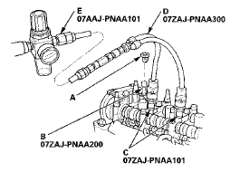
. VTEC Air Stopper 07ZAJ-PNAA200
. VTEC Air Adapter 07ZAJ-PNAA101 (2)
. Air Joint Adapter 07ZAJ-PNAA300
- Air Pressure Regulator 07AAJ-PNAA101
1. Start the engine, and let it run for 5 minutes, then turn the ignition switch to LOCK (0).
2. Remove the cylinder head cover (see page 6-24).
3. Set the No. 1 piston at top dead center (TDC) (see step 5 on page 6-13).
4. Move the secondary rocker arm (A) for the No. 1 cylinder. The secondary rocker arm should move independently of the mid rocker arm (B).
- If the secondary rocker arm moves freely, go to step 5.
- If the secondary rocker arm does not move independently, remove the mid, primary, and secondary rocker arms as an assembly, and check that the pistons in the rocker arms move smoothly.
If any rocker arm needs replacing, replace the mid, primary, and secondary rocker arms as an assembly, then retest.

5. Repeat step 4 on the remaining secondary rocker arms with each piston at TDC. When all the secondary rocker arms pass the test, go to step 6.
6. Check that the air pressure on the shop air compressor gauge indicates over 400 kPa (4.0 kgf/cm2, 57 psi).
7. Inspect the valve clearance (see page 6-9).
8. Remove the sealing bolt (A) from the relief hole, and install the VTEC air stopper (B).

9. Remove the No. 2 and No. 3 camshaft holder bolts, and install the VTEC air adapters (C) finger-tight.
10. Connect the air joint adapter (D) and the air pressure regulator (E).
11. Loosen the valve on the air pressure regulator, and apply the specified air pressure.
Specified Air Pressure: 290 kPa (3.0 kgf/cm2,42 psi)
NOTE: If the rocker arm piston does not move after applying air pressure; move the rocker arm up and down manually by rotating the crankshaft clockwise.
13. Intake side: With the specified air pressure applied, move the secondary rocker arm (A) for the No. 1 cylinder. The mid rocker arm (B), the primary rocker arm (C), and the secondary rocker arm should move together.
- If the mid, the primary, and the secondary rocker arms move together, go to step 14.
- If the mid and primary rocker arms do not move together with the secondary rocker arm, remove the mid, primary, and secondary rocker arms as an assembly, and check that the pistons in the rocker arms move smoothly. If any rocker arm needs replacing, replace the mid, primary, and secondary rocker arms as an assembly, then retest.

14. Exhaust side: With the specified air pressure applied, move the secondary rocker arm (A) for the No. 1 cylinder. The primary rocker arm (B) and the secondary rocker arm should move together.
- If the primary and the secondary rocker arms move together, go to step 15.
- If the primary rocker arms do not move together with the secondary rocker arm, remove the primary and the secondary rocker arms as an assembly, and check that the pistons in the rocker arms move smoothly. If any rocker arm needs replacing, replace the primary and the secondary rocker arms as an assembly, then retest.

15. Repeat step 13 through 14 on the remaining secondary rocker arms with each piston at TDC. When all the secondary rocker arms pass the test, go to step 16.
16. Remove the air pressure regulator, the air joint adapter, the VTEC air adapter, and the VTEC air stopper.
17. Torque the camshaft holder mounting bolts to 22 N-m (2.2 kgfm, 16 Ibfft).
18. Torque the sealing bolt to 10 Nm (1.0 kgf-m, 1 A Ibfft).
19. Install the cylinder head cover (see page 6-74).
 Cylinder Head
Component Location Index (cont'd)
Engine Compression Inspection
NOTE: After this inspection, you must reset the engine
control module (ECM)/powertrain control module
(PCM), otherwise the ECM ...
 VTC Actuator Inspection
1. Remove the cam chain (see page 6-62).
2. Loosen the rocker arm adjusting screws (see step 2 on
page 6-81).
3. Remove the camshaft holder (see step 3 on page
6-81).
4. Remove the intake c ...
See also:
Rear Seat-back Release Lever/Cable
Removal/Installation
NOTE:
- Take care not to bend or scratch the interior trim.
- 4-door is shown; 2-door is similar.
1. Remove the rear shelf (see page 20-128).
2. Disconnect the seat-back release cable (A) fr ...
Rear Seat Access
Driver’s Side
On all V6 models and 4-cylinder EX-L
model
To get into the rear seat on the
driver’s side, open the door and pull
the release lever up on the side of
the seat-back. The s ...
Accessory Power Sockets
Your vehicle has two accessory
power sockets; one is at the front of
the center console and the other is in
the console compartment.
To use an accessory power socket,
the ignition switch mu ...
