 Honda Accord: Tire Pressure Sensor Location
Special Tools Required
TPMS Trigger Tool ATEQ VT55*
*Available through the Honda Tool and Equipment Program 888-424-6857
NOTE: - The TPMS tool is necessary to do this procedure.
- Let the vehicle sit for at least 5 minutes to allow the tire pressure sensors to switch to sleep mode.
-This procedure locates where the tire pressure sensors 1, 2, 3,4 are mounted, when activated by the TPMS tool.
-Position the vehicle at least 10 ft (3 m) away from other vehicles that have tire pressure sensors.
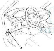
1. With the ignition switch in LOCK (0), connect the HDS to the data link connector (DLC) (A) located under the driver's side of the dashboard.
2. Turn the ignition switch to ON (II).
3. Make sure the HDS communicates with the vehicle and the TPMS control unit. If it does not, troubleshoot the DLC circuit (see page 11-181).
4. Using the HDS, bring up the TPMS data list, scroll down to the bottom, and locate the four tire pressure sensors ID numbers. These are the ID numbers assigned to each tire location.
5. Follow HDS screen prompts under sensor ID learn, to turn on the TPMS tool.
6. Hold the TPMS tool near the valve stem of one wheel, and activate the tire pressure sensor.
NOTE: - See the HDS Help menu under sensor ID learn for specific instructions.
- If the tire pressure sensor still does not respond, then check for DTC 32,34,36, and 38 with the HDS.
7. The TPMS tool will display the sensor data including the sensor ID number.
8. Locate the tire pressure sensor ID numbers on the TPMS data list, and match it to the sensor number.
Note the sensor location.
9. Turn the ignition switch to LOCK (0).
 Memorizing the Tire Pressure Sensor ID
Special Tools Required
TPMS Trigger Tool ATEQ VT55*
- Available through the Honda Tool and Equipment
Program 888-424-6857
All four tire pressure sensor IDs must be memorized to
the TPMS control u ...

See also:
Emergency Engine Stop
If you cannot stop the engine by pressing the ENGINE START/STOP
button, do
either of the following operations:
• Press and hold the ENGINE START/STOP button for about two seconds.
• Firmly ...
Circuit Diagram
...
Fog Lights
If equipped
Turn the fog lights on and off by
turning the switch next to the
headlight switch.
You can use the fog lights only when
the headlights are on low beam.
With the light switch in ...