 Honda Accord: Subframe Replacement
Special Tools Required
Subframe Alignment Pin 070AG-SJAA10S
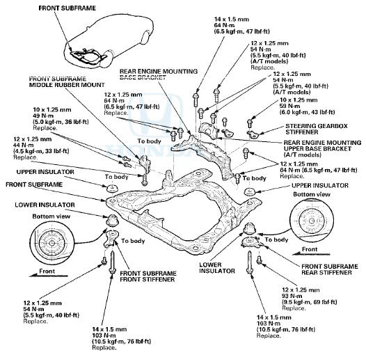
Front Subframe Torque
After removing the subframe mounting bolts, the front subframe middle rubber mount mounting bolts, the front subframe rear stiffener mounting bolts, and the rear engine mounting base bracket mounting bolts, be sure to replace them with new ones.
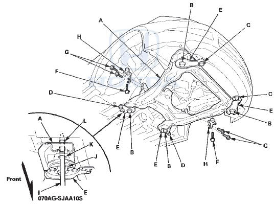
Front Subframe Alignment
NOTE: Align the front subframe with the subframe alignment pin.
1 Align the front subframe (A) in the following sequence.
-1. Lift the front subframe up to the body, and loosely install the new subframe mounting bolts (B), the front stiffener mounting bolts (C), the new rear stiffener mounting bolts (D) and the stiffeners (E).
-2. Loosely install the new subframe middle mounting bolts (F, G) securing the subframe middle mounts (H).
-3. Insert the subframe alignment pin (I) through the positioning slot (J) on the right rear stiffener, through the positioning hole (K) on the subframe, and into the positioning hole (L) on the body, then loosely tighten the subframe right rear mounting bolt.
-4. Insert the subframe alignment pin through the positioning slot on the left rear stiffener, through the positioning hole on the subframe, and into the positioning hole on the body, then loosely tighten the subframe left rear mounting bolt.
-5. Tighten the subframe mounting bolts to the specified torque values starting with the right rear subframe mounting bolt. Use the subframe alignment pin when tightening the rear side subframe mounting bolts.
-6. Check all of the subframe mounting bolts, and retighten if necessary.
NOTE: Tighten the bolts in the sequence shown.
2. Tighten the bolts securing the subframe middle mounts to the specified torque.
3. After reinstalling all removed parts, check and adjust the front wheel alignment (see page 18-5).
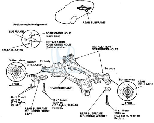
Rear Subframe Torque
NOTE: - Install the rear subframe by aligning the installation positioning holes and positioning holes with the subframe alignment pin.
- Always replace any removed subframe mounting bolts with new ones.
 Middle Crossmember Gusset
Replacement
Middle Crossmember Gusset
Replacement
2-door
NOTE: Take care not to scratch the body.
1. Remove the rear side trim panel (see page 20-127).
2. Pull back the rear part of the carpet as needed.
3. Remove the bolts (A, B), then rem ...
 Frame Repair Chart
Top View
g2 Front floor locating hole 025 (0.98) rear
h2 Front floor tunnel frame locating hole 013 (0.51) rear
i Rear frame A locating hole 025 (0.98)
j Rear floor locating hole 025 (0.98)
k1 ...
See also:
Steering Wheel Rotational Play Check
1. Set the front wheels in the straight ahead position.
2. Measure how far you can turn the steering wheel left
and right without moving the front wheels.
-If the play is within the limit, the ...
Shifting
• Shift Lever Operation
Fully depress the clutch pedal to operate the shift lever and change gears,
then
slowly release the pedal.
Depress the clutch pedal, and pause for a few seconds before ...
Outside Air Temperature Sensor Test
1 Remove the outside air temperature sensor (see page
22-353).
2. Dip the sensor in ice water, and measure the
resistance. Then pour warm water on the sensor, and
check for a change in resistanc ...