 Honda Accord: Side Sill Protection Tape Replacement
2-door
1. Slowly remove the old side sill protection tape.
2. Clean the body bonding surface with a shop towel dampened in isopropyl alcohol. After cleaning, keep oil, grease, and water from getting on the surface.
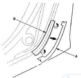
3. Remove the adhesive backing B from the side sill protection tape (C).
NOTE: Do not remove adhesive backing A.
4. Align the corner (B) of the adhesive backing A with the body line (C). Then align the adhesive backing edge (D) with the body line (E). Press the exposed adhesive area of the side sill protection tape (F) against the body.
5. Remove the adhesive backing A from the side sill protection tape (B), and press the tape into place.
4-door
1. Slowly remove the old side sill protection tape.
2. Clean the body bonding surface with a shop towel dampened in isopropyl alcohol. After cleaning, keep oil, grease, and water from getting on the surface.
3. Remove the adhesive backing B from the side sill protection tape (C).
NOTE: Do not remove the adhesive backing A.
4. Align the alignment marks (B) of the adhesive backing A with the body line (C). Then align the alignment mark (D) on the adhesive backing with the round body bulge (E). Press the exposed adhesive area of the side sill protection tape (F) against the body.
5. Remove the adhesive backing A from the side sill protection tape (B), and press the tape into place.
 Roof Molding Replacement
Special Tools Required
KTC Trim Tool S e t SOJATP2014*
* Available through the Honda Tool and
Equipment
Program; call 888-424-6857
Molding Replacement
NOTE:
- Put on gloves to protect your han ...
 Trunk Lower Trim Replacement
4-door
NOTE:
- Put on gloves to protect your hands.
- Take care not to scratch the trunk lid.
1. Remove the license plate from the trunk lid.
2. Remove the clips fastening the trunk lower t ...
See also:
Replacing a Front Side Marker Light Bulb
1. To change the bulb on the driver’s
side, start the engine, turn the
steering wheel all the way to the
right, then turn off the engine. To
change the bulb on the passenger’s
side, tu ...
Steering Angle Sensor Replacement
SRS components are located In this area. Review the SRS component locations:
4-door (see page 24-21), 2-door (see
page 24-23) and the precautions and procedures (see page 24-25).
NOTE: Do not da ...