
 Honda Accord: Rocker Arm Oil Control Valve
Removal/Installation
Honda Accord: Rocker Arm Oil Control Valve
Removal/Installation
All models except PZEV
1. Remove the strut brace (see page 20-306).
2. Disconnect the rocker arm oil control solenoid connector (A) and the rocker arm oil pressure switch connector (B).
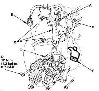
3. Remove the harness clamps (C) and the bolts (D).
4. Remove the rocker arm oil control valve assembly (E) and the rocker arm oil control valve filter (F).
5. Remove the engine wire harness bracket (A) (also (B) (if equipped)) from the rocker arm oil control valve (C).
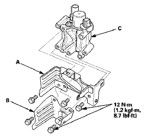
6. Install the parts in the reverse order of removal with a new rocker arm oil control valve filter.
PZEV model
1. Remove the strut brace (see page 20-306).
2. Disconnect the rocker arm oil control solenoid A connector-(A), the rocker arm oil control solenoid B connector (B), the rocker arm oil pressure switch A connector (C), and the rocker arm oil pressure switch B connector (D).
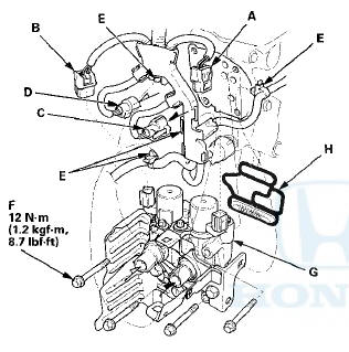
3. Remove the harness clamps (E) and the bolts (F).
4. Remove the rocker arm oil control valve assembly (G) and the rocker arm oil control valve filter (H).
5. Remove the engine wire harness bracket (A) (also (B) (if equipped)) from the rocker arm oil control valve (C).
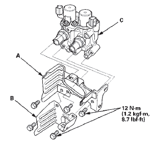
6. Install the parts in the reverse order of removal with a new rocker arm oil control valve filter.
 CMP Sensor A Replacement
1. Disconnect the CMP sensor A 3P connector (B).
2. Remove CMP sensor A from the intake camshaft side
of the cylinder head.
3. Install the parts in the reverse order of removal with a
new O-ri ...
 Rocker Arm Oil Pressure Switch
Removal/Installation
Rocker Arm Oil Pressure Switch
Removal/Installation
All models except PZEV
1. Disconnect the rocker arm oil pressure switch
connector (A).
2. Remove the rocker arm oil pressure switch (B).
3. Install the parts in the reverse order of removal wi ...
See also:
Audio System Theft Protection*
The audio system is disabled when it is disconnected from the power source,
such as
when the battery is disconnected or goes dead.
• Reactivating the audio system
1. Set the power mode to ON, ...
Outside Air Temperature Sensor
Replacement
1 Disconnect the 2P connector (A) from the outside air
temperature sensor (B).
2. Lift the tab (C) to release the lock, then remove the
outside air temperature sensor from the front
bumper.
3 ...
Using the Remote Transmitter
Press the trunk release button for
approximately one second to unlock and open
the trunk.
...