
 Honda Accord: Power Window Master Switch Input
Test
Honda Accord: Power Window Master Switch Input
Test
NOTE: Before testing, troubleshoot the multiplex integrated control unit first, using B-CAN System Diagnosis Test Mode A (see page 22-134).
1. Turn the ignition switch to LOCK (0), open and close the driver's door, then remove the power window master switch.
• 4-door (see page 22-305)
• 2-door (see page 22-306)
2. Disconnect the 37P connector (A) from the door power window master switch (B).
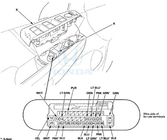
The illustration shows 4-door.
3. Inspect the connector and socket terminals to be sure they are all making good contact.
• If the terminals are bent, loose or corroded, repair them as necessary and recheck the system.
• If the terminals look OK, go to step 4.
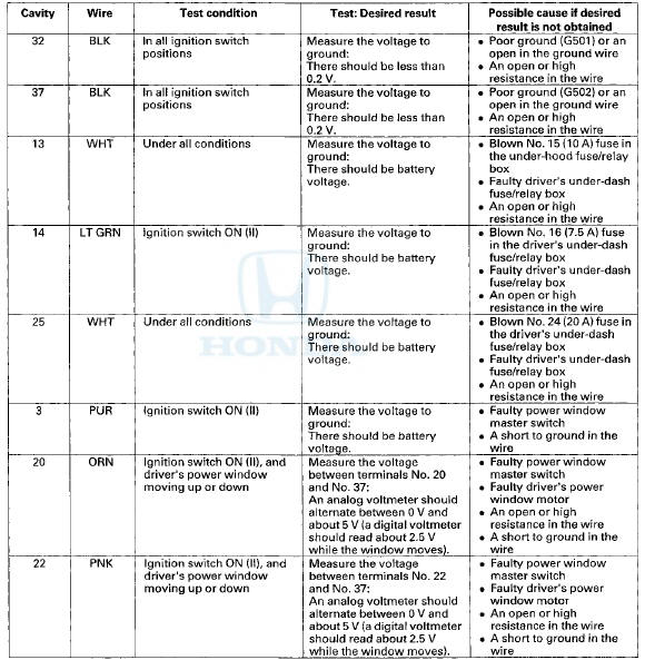
4. Reconnect the connector to the power window master switch, turn the ignition switch to ON (II), and do these input tests at the following connector.
• If any test indicates a problem, find and correct the cause, then recheck the system.
• If all the input tests prove OK, go to step 5.
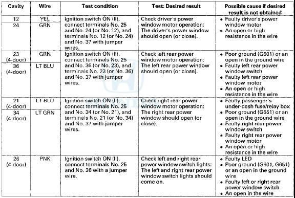
5. Turn the ignition switch to LOCK (0), open and close the driver's door, then disconnect the 37P connector from the power window master switch again.
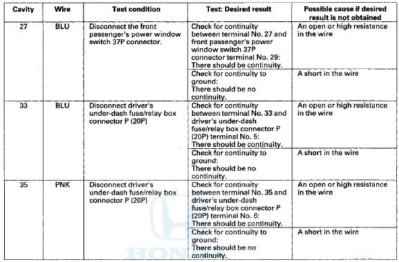
6. With the connector stiii disconnected, do these input tests at the following connector.
• If any test indicates a problem, find and correct the cause, then recheck the system.
• If all the input tests prove OK, the door multiplex control unit must be faulty, replace the power window master switch.
- 4-door (see page 22-305)
- 2-door (see page 22-306)
NOTE: After replacing the power window master switch, reset the power window control unit (see page 22-280).
 DTC Troubleshooting
DTC B112S; Driver's Power Window Motor A
Pulse Malfunction
DTC B1126: Driver's Power Window Motor B
Pulse Malfunction
NOTE: If you are troubleshooting multiple DTCs, be sure
to follow the instruc ...
 Front Passenger's Power Window
Switch Input Test
Front Passenger's Power Window
Switch Input Test
1. Turn the ignition switch to LOCK (0), open and close the driver's door,
then remove the front passenger's power
window switch.
• 4-door (see page 22-306)
• 2-door (see page 22-307)
...
See also:
Circuit Diagram
...
DTC Troubleshooting Index
NOTE: Record all DTCs, and sort them by DTC type using the DTC
troubleshooting index, then troubleshoot the DTC(s)
in this order:
• Battery voltage DTCs
• Internal error DTCs
• Lo ...