 Honda Accord: Mainshaft Assembly Clearance Inspection
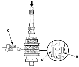
1. Support the bearing Inner race with an appropriate sized socket ( A ) , and push down on the mainshaft ( B ) .
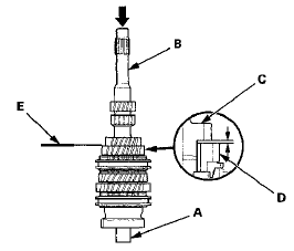
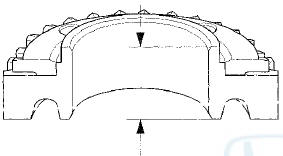
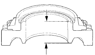
2. Measure the clearance between 2nd gear (C) and 3rd gear (D) with a feeler gauge (E).
- If the clearance exceeds the service limit, go to step 3.
- If the clearance is within the service limit, go to step 4.
Standard: 0.06-0.16 mm (0.002-0.006 in)
Service Limit: 0.25 mm (0.010 in)
3. Measure the thickness of 3rd gear.
- If the thickness is less than the service limit, replace 3rd gear.
- If the thickness is within the service limit, replace the 3rd/4th synchro hub and the 3rd/4th synchro sleeve as a set.
Standard: 23.92-23.97 mm (0.942-0.944 in)
Service Limit: 23.80 mm (0.937 in)
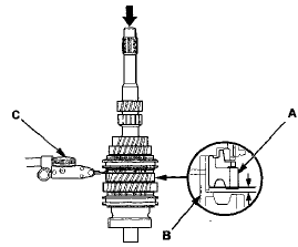
4. Measure the clearance between 4th gear ( A ) and the 4th/5th gear distance collar ( B ) with a dial indicator (C).
- If the clearance exceeds the service limit, go to step 5.
e If the clearance is within the service limit, go to step 7.
Standard: 0.06-”0.16 mm (0.002-0.006 in)
Service Limit: 0.25 mm (0.010 in)
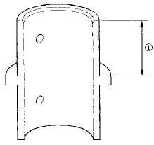
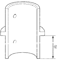
5. Measure the length of the
4th/5th gear distance
collar as shown.
- If the length  is not within the
standard, replace
the 4th/5th gear distance collar,
- If the length
is within the standard, go to step 6.
Standard: 24.03-24.08 mm (0.946-0.948 in)
6. Measure the thickness of 4th gear, - If the thickness is less than the service limit, replace 4th gear.
- Sf the thickness is within the service limit, replace the 3rd/4th synchro hub and the 3rd/4th synchro sleeve as a set.
Standard: 23.92-23.97 mm (0.942-0.944 in)
Service Limit: 23.80 mm (0.937 in)
7. Measure the clearance between the 4th/5th gear distance collar (A) and 5th gear (B) with a dial indicator (C).
- If the clearance exceeds the service limit, go to step 8.
- If the clearance is within the service limit, go to step 10.
Standard: 0.06-0.16 mm (0.002-0.006 in)
Service Limit: 0.25 mm (0.010 in)
8. Measure the length  of the
4th/5th gear distance
collar as shown.
- If the length  is not within the
standard, replace
the 4th/5th gear distance collar.
- If the length is within the
standard, go to step 9.
Standard: 24.03-24.08 mm (0.946-0.948 in)
9. Measure the thickness of 5th gear.
- If the thickness is less than the service limit, replace 5th gear.
- If the thickness is within the service limit, replace the 5th synchro hub and 5th synchro sleeve as a set.
Standard: 23.92-23.97 mm (0.942-0.944 in)
Service Limit: 23.80 mm (0.937 in)
10. Measure the length of the MBS distance collar. If the length is not within standard, replace the MBS distance collar.
Standard: 23.95-24.05 mm (0.943-0.947 in)
 Shift Fork Disassembly/Reassembly
NOTE: Prior to reassembling, clean all the parts in solvent, dry them, and
apply MTF to all contact surfaces
...
 Mainshaft Disassembly
NOTE: Refer to the Exploded View in the Mainshaft
Reassembly, as needed, when removing components
pressed onto the mainshaft (see page 13-38).
1. Remove the angular ball bearing (A) and the taper ...
See also:
Wheel Runout Inspection
1. Raise and support the vehicle (see page 1 -13).
2. Check for a bent or deformed wheel.
3. Set up the dial gauge as shown, and measure the
axial runout by turning the wheel.
Front and rear w ...
Introduction
One of the best ways to enhance the enjoyment of your new vehicle is to
read this manual. In it, you will learn how to operate its driving controls and
convenience items. Afterwards, keep this own ...
DTC Troubleshooting
DTC indicator A: Climate Control Unit Internal
Error
NOTE: Check the battery condition (see page 22-90) and
the charging system (see page 4-25).
1. Turn the ignition switch to LOCK (0), and then ...