 Honda Accord: DTC Troubleshooting
DTC 1001:
FROM System info Error
NOTE: • Check the vehicle battery condition first (see page 22- 9 0 ) .
• Before you troubleshoot, make sure to follow the General Troubleshooting Information (see page 23- 130).
1. Turn the ignition switch to LOCK (0) and then back to ON (II).
2. Check for the hard error code (see page 23-138).
is DTC 1001 indicated? YES
-Replace the navigation unit (see page 23-238), because there is an internal problem with the Flash-ROM .
NO
-lntermittent failure, the system is OK at this time.
If the vehicle repeatedly comes back with the DTC, replace the navigation unit (see page 23-238).
DTC 1101:
Media Bus Send Error
NOTE: • Check the vehicle battery condition first (see page 22- 9 0 ) .
• Before you troubleshoot, make sure to follow the General Troubleshooting Information (see page 23- 130).
1. Clear hard error code (see page 23-139).
2. Turn the ignition switch to LOCK (0) and then back to ON (II).
3. Check for the hard error code (see page 23-138).
is DTC 1101 indicated? YES
-Replace the navigation unit (see page 23-238).
NO
-lntermittent failure, the system is OK at this time.
If the vehicle repeatedly comes back with the DTC, replace the navigation unit (see page 23-238).
DTC 1201:
DVD High Temp
NOTE: • Check the vehicle battery condition first (see page 22- 90).
• Before you troubleshoot, make sure to follow the General Troubleshooting Information (see page 23- 130).
• This code sets when the internal temperature of the navigation unit ECU rises above 158 °F (70 °C). The navigation unit is designed to shut down to protect the navigation unit ECU. This could be caused by an inoperative navigation unit ECU fan or if the trunk temperature exceeds the maximum. Do the troubleshooting when the unit is within the allowable temperature range.
1. Check that the temperature is below 158 В°F (70 В°C) in the trunk.
2. Clear the hard error code (see page 23-139).
3. Turn the ignition switch to LOCK (0) and then back to ON (II).
4. Check for the hard error code (see page 23-138).
Is DTC 1201 indicated? YES
-Replace the navigation unit (see page 23-238).
NO
-lntermittent failure, the system is OK at this time.
If the vehicle repeatedly comes back with the DTC, replace the navigation unit (see page 23-238).
DTC 1202:
DVD Low Temp
NOTE: • Check the vehicle battery condition first (see page 22- 90).
• Before you troubleshoot, make sure to follow the General Troubleshooting Information (see page 23- 130).
• This code sets when the internal temperature of the navigation unit ECU falls below - 4 °F (-20 °C). The navigation unit is designed to shut down to protect the navigation unit ECU. This is usually caused by very cold exterior temperatures. Do the troubleshooting when the unit is within the allowable temperature range.
1. Check that the temperature is above —4°F(—20 °C)in the trunk.
2. Clear the hard error code (see page 23-139).
3. Turn the ignition switch to LOCK (0) and then back to ON (II).
4. Check for the hard error code (see page 23-138).
Is DTC 1202 indicated? YES
-Replace the navigation unit (see page 23-238).
NO
-lntermittent failure, the system is OK at this time.
If the vehicle repeatedly comes back with the DTC, replace the navigation unit (see page 23-238).
DTC 1301:
GPS Antenna Error
NOTE: • Check t h e vehicle battery condition first (see page 2 2 - 9 0 ) .
• Before you troubleshoot, make sure to follow the General Troubleshooting Information (see page 23- 130).
• Make sure the vehicle is parked outside, away from buildings.
• Aftermarket electronic devices located near the navigation unit or GPS antenna can potentially interfere with the operation of the navigation system.
1. Clear the hard error code (see page 23-139).
2. Turn the ignition switch to LOCK (0) and then back to ON (II).
3. Check for the hard error code (see page 23-138).
Is DTC 1301 indicated? YES
-Go to step 4.
NO
-lntermittent failure, the system is OK at this time.
4. Turn the ignition switch to LOCK (0).
5. Check for poor connections or loose terminals at the navigation unit connector E (2P).
6. Clear the hard error code 7. Turn the ignition switch to LOCK (0) and then back to ON (II).
8. Check for the hard error code.
Is DTC 1301 indicated? YES
-Go to step 9.
NO
-lntermittent failure, the system is OK at this time.
9. Turn the ignition switch to LOCK (0).
10. Replace a known-good GPS antenna (see page 23-240).
11. Turn the ignition switch to ON (II).
12. Clear the hard error code.
13. Turn the ignition switch to LOCK (0) and then back to ON (II).
14. Check for the hard error code.
Is DTC 1301 indicated? YES
-Replace the original GPS antenna.11 NO
-lntermittent failure, the system is OK at this time.
If t h o weu;c | c repeatedly comes back with the DTC, replace the navigation unit (see page 23-238).
DTC 1302:
GPS Receiver Error 1
NOTE: • Check t h e v e h i c l e battery c o n d i t i o n f i r s t (see page 22- 90).
• Before y o u t r o u b l e s h o o t make s u r e t o f o l l ow t he General T r o u b l e s h o o t i n g I n f o r m a t i o n (see page 23- 130).
• Make sure t h e v e h i c l e is parked outside, a w a y f r om b u i l d i n g s .
• Aftermarket electronic devices located near t he navigation unit or GPS antenna can p o t e n t i a l ly interfere w i t h t h e o p e r a t i o n o f t h e n a v i g a t i o n system.
1. Clear t h e h a r d error code (see p a g e 23-139).
2. T u r n t h e i g n i t i o n s w i t c h t o LOCK (0) a n d t h e n back to ON (II).
3. Check f o r t h e h a r d error code (see page 23-138).
Is DTC 1302 indicated? YES
-Go t o s t ep 4.
NO
-lntermittent f a i l u r e , t h e s y s t em is OK a t t h is time.
4. T u r n t h e i g n i t i o n s w i t c h t o LOCK (0).
5. Check f o r p o o r connections o r l o o s e t e r m i n a l s at t h e navigation unit connector E (2P).
6. Clear t h e h a r d error code.
7. T u r n t h e i g n i t i o n s w i t c h t o LOCK (0) a n d t h e n back to ON (II).
8. Check f o r t h e h a r d error code.
Is DTC 1302 indicated? YES
-Go t o s t ep 9.
NO
-lntermittent f a i l u r e , t h e s y s t em is OK a t t h is time.
9. T u r n t h e i g n i t i o n s w i t c h t o LOCK (0).
10. Replace a k n o w n - g o o d GPS antenna (see page 23-240).
11. T u r n t h e i g n i t i o n s w i t c h t o ON (II).
12. Clear t h e h a r d error code.
13. T u r n t h e i g n i t i o n s w i t c h t o LOCK (0) a n d t h e n back to ON (II).
14. Check f o r t h e h a r d e r r o r code.
Is DTC 1302 indicated? YES-
Replace t h e o r i g i n a l GPS a n t e n n a . NO
-lntermittent f a i l u r e , t h e s y s t em is OK at t h i s t i m e.
If t h e v e h i c le repeatedly comes back w i t h t he DTC, replace t h e n a v i g a t i o n unit (see p a g e 2 3 - 2 3 8 ).
PTC 1303:
GPS Receiver Error 2
NOTE: • Check the vehicle battery condition first (see page 22- 90).
• Before you troubleshoot, make sure to follow the General Troubleshooting Information (see page 23- 130).
• Make sure the vehicle is parked outside, away from buildings.
• Aftermarket electronic devices located near the navigation unit or GPS antenna can potentially interfere with the operation of the navigation system.
1. Clear the hard error code (see page 23-139).
2. Turn the ignition switch to LOCK (0) and then back to ON fill.
3. Check for the hard error code (see page 23-138).
Is DTC 1303 indicated? YES
-Replace the navigation unit (see page 23-238).
NO
-lntermittent failure, the system is OK at this time.
If the vehicle repeatedly comes back with the DTC, replace the navigation unit (see page 23-238).
DTC 1304:
Gyro Error 1
NOTE: • Check the vehicle battery condition first (see page 22- 90).
• Before you troubleshoot, make sure to follow the General Troubleshooting Information (see page 23- 130).
• Make sure the vehicle is parked outside, away from buildings.
• Aftermarket electronic devices located near the navigation unit or GPS antenna can potentially interfere with the operation of the navigation system.
1. Clear hard error code (see page 23-139).
2. Turn the ignition switch to LOCK (0) and then back to ON (II).
3. Check for the hard error code (see page 23-138).
Is DTC 1304 indicated? YES
-Replace the navigation unit (see page 23-238).
NO-
lntermittent failure, the system is OK at this time.
If the vehicle repeatedly comes back with the DTC, replace the navigation unit (see page 23-238).
DTC 1305
: Gyro Error 2:ECU Temp XX В°C
NOTE: • Check the vehicle battery condition first ( s e e page 22- 90).
• Before you troubleshoot, make sure to follow the General Troubleshooting Information (see page 23- 130).
• Aftermarket electronic devices located near the navigation unit or GPS antenna can potentially interfere with the operation of the navigation system.
1. Check that the trunk temperature i s between —4°F {— 20 °C) and 158 °F (70 °C).
2. Clear hard error code (see page 23-139).
3. Turn the ignition switch to LOCK (0) and then back to ON (II).
4. Check for the hard error code (see page 23-138).
Is DTC 1304 indicated? YES
-Replace the navigation unit (see page 23-238).
NO-
lntermittent failure, the system is OK at this time.
Ifthe vehicle repeatedly comes back with the DTC, replace the navigation unit (see page 23-238).
DTC 1306:
Vehicle Speed Pulse
NOTE: • Check the vehicle battery condition first (see page 22- 90).
• Before you troubleshoot, make sure to follow the General Troubleshooting Information (see page 23- 130).
1. Clear the hard error code (see page 23-139).
2. Turn the ignition switch to LOCK (0), and then start the engine.
3. Check for the hard error code (see page 23-138).
Is DTC 1306 indicated? YES
-Go to step 4.
NO
-lntermittent failure, the system is OK at this time.B 4. Drive the vehicle and watch the VSP signal.
Does the VSP signal change from [0] to [1] as you drive? YES
-Replace the navigation unit (see page 23-238).
NO
-Do the symptom troubleshooting for Vehicle position icon constantly leaves road, moves erratically or is very far from actual position (see page 23-21 B).
DTC 1307:
DVD Read Error
NOTE: • Check the vehicle battery condition first (see page 22- 90).
• Check any official Honda service website for more information about the navigation system and software updates.
• Before you troubleshoot make sure to follow the General Troubleshooting Information (see page 23- 130).
• Inspect the navigation DVD for scratches or damage.
1. Check the navigation DVD.
Is the navigation DVD the correct color and version for the vehicle? Is it scratch free? YES
-Go to step 2.
NO
-Replace the navigation DVD and retest.
2. Turn the ignition switch to ON (II).
Is there a DVD error message? YES
-Go to DVD screen error messages (see page 23-229).
NO
-Go to step 3. 3. Clear the hard error code (see page 23-139).
4. Turn the ignition switch to LOCK (0) and then back to ON (ll).
5. Check for the hard error code (see page 23-138).
Is DTC 1307 indicated? YES
-Replace the navigation unit (see page 23-238).H NO
-lntermittent failure, the system is OK at this time.
If the vehicle repeatedly comes back with the DTC, replace the navigation unit (see page 23-238).
DTC1402:
Audio Error 2
NOTE: • Check the vehicle battery condition first (see page 22- 90).
• Before you troubleshoot, make sure to follow the General Troubleshooting Information (see page 23- 130).
1. Clear the hard error code (see page 23-139).
2. Turn the ignition switch to LOCK (0) and then back to ON (II).
3. Check for the hard error code (see page 23-138).
Is DTC 1402 indicated? YES
-Check if the audio unit functions are working properly. If any problems are found, go to affected troubleshooting in audio section.
NO
-lntermittent failure, the system is OK at this time.
DTC 1403;
Audio Error 3
NOTE: • Check the vehicle battery condition first (see page 22- 90).
• Before you troubleshoot, make sure to follow the General Troubleshooting Information (see page 23- 130).
1. Clear the hard error code (see page 23-139).
2. Turn the ignition switch to LOCK (0) and then back to ON (II).
3. Check for the hard error code (see page 23-138).
Is DTC 1403 indicated? YES
-Replace the navigation unit (see page 23-238).H NO
-lntermittent failure, the system is OK at this tirne.
DTC 1409:
Audio Error 9
NOTE: •Check the vehicle battery condition first (see page 22- 90).
• Before you troubleshoot, make sure to follow the General Troubleshooting Information (see page 23- 130).
1. Clear the hard error code (see page 23-139).
2. Turn the ignition switch to LOCK (0) and then back to ON (II).
3. Check for the hard error code (see page 23-138).
Is DTC 1409 indicated? YES
-Check the XM error codes (see page 23-65). If any codes are detected, go to affected troubleshooting in audio (XM) section.
NO
-lntermittent failure, the system is OK at this t i m e.
PTC 1501:
Aircon Error
PTC 2703:
Aircon Diag
N O T E : • Check the vehicle battery condition first (see page 22- 90).
• Check for B-CAN DTCs and resolve them before troubleshooting.
• Before you troubleshoot make sure to follow the General Troubleshooting Information (see page 23- 130).
• DTC 1501 and/or 2703 can be stored when the ignition switch is at ACCESSORY (I). With the ignition switch is in ACCESSORY (I), the climate control unit is turned off and the navigation unit loses communication and stores DTCs. Therefore, there is a possibility that the system is normal even DTC 1501 and/or 2703 is stored.
Check System Links (see page 23-176) with the engine running, and if it shows normal, the system is OK at this time. If not, do this troubleshooting.
1. Clear the hard error code (see page 23-139).
2. Turn the ignition switch to LOCK (0) and then back to ON (II).
3. Go into the Diagnostic Menu, and select the Self-Diagnosis Mode in the Select Diagnosis Items menu (see page 23-176).
4. Check the System Links.
Is the A/C icon red? YES
-Go to step 5.
NO
-lntermittent failure, the system is OK at this t i m e .
5. Turn the ignition switch to LOCK (0).
6. Disconnect navigation unit connector B (32P).
7. Connect navigation unit connector B (32P) terminals No. 4, No. 20, and No. 21 with a jumper wire.
NAVIGATION UNIT CONNECTOR B (32P)
Wire side of female terminals
8. T u r n t h e i g n i t i o n s w i t c h to ON (111.
9. Do the climate control Self-Diagnostic Mode (see page 21-101).
Are both HE A T/VENT indicators solid with the remaining icons blinking? YES
-Replace the navigation unit (see page 23-238).
NO
-Go to step 10.
10. Turn the ignition switch to LOCK (0), then disconnect the jumper wire.
11. Disconnect climate control unit connecter B (12P).
12. Connect climate control unit connector B (12P) terminals No. 7, No. 8, and No. 9 with a jumper wire.
CLIMATE CONTROL UNIT CONNECTOR B (12P)
Wire side of female terminals
13. Check f o r continuity between navigation unit connector B (32P) terminals No. 4 , No. 20, and between terminals No. 20 and No. 21.
NAVIGATION UNIT CONNECTOR B (32P)
Wire side of female terminals
Is there continuity? YES
-Go to step 14.
NO
-Repair an open in the wire(s) between the navigation control unit and the climate control unit.Li 14. Disconnect the jumper wire.
15. Check for continuity between body ground and navigation unit connector B (32P) terminals No. 4, No. 20, and No. 21 individually.
NAVIGATION UNIT CONNECTOR B (32P)
Wire side of female terminals
Is there continuity? YES
-Repair a short to body ground in the wire(s) between the navigation control unit and the climate control unit.
NO
-Go to step 16.
16. Check for continuity between the terminal of navigation unit connector B (32P) according to the table.
NAVIGATION UNIT CONNECTOR B (32P)
Wire side of female terminals
Is there continuity? YES
-Repair a short in the wire(s) between the navigation unit and climate control unit.H NO
-Go to step 17.
17. Turn the ignition switch to ON (II).
18. Measure the voltage between body ground and navigation unit connector B (32P) terminals No. 4, No. 20, and No. 21 individually.
NAVIGATION UNIT CONNECTOR B (32P)
Wire side of female terminals
Is there more than 0.2 V? YES
-Repair a short to power in the wire(s) between the navigation unit and the climate control unit.
NO
-Replace the climate control unit (see page 21-190).
DTC 2601:
D i s p l a y Diag: Connect
NOTE: • Check t h e vehicle battery condition first (see page 22- 90).
• Check f o r B-CAN DTCs a n d resolve them before troubleshooting.
• Before you troubleshoot, make sure to follow the General Troubleshooting Information (see page 23- 130).
1. Clear the hard error code (see page 23-139).
2. Turn the ignition switch to LOCK (0) and then back to ON (II).
3. Go into the Diagnostic Menu, and select the Self-Diagnosis Mode in the Select Diagnosis Items menu (see page 23-176).
4. Check the System Links.
Is the Display icon red? YES
-Go to step 5.
NO
-lntermittent failure, the system is OK at this t i m e . 5. Check for poor connections or loose terminals at navigation unit connector B (32P), audio unit connector E (14P), and XM receiver connector A (14P).
Are the connections OK? YES
-Go to step 6.
NO
-Repair poor connections or loose terminals, and recheck the Self-Diagnosis Mode (see page 23-176).
6. Turn the ignition switch to LOCK (0).
7. Disconnect navigation unit connector B (32P) and the navigation display unit 28P connector.
8. Connect the navigation unit connector B (32P) terminals No. 10 and No. 26 with a jumper wire.
NAVIGATION UNIT CONNECTOR B (32P)
Wire side of female terminals
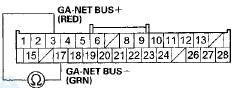
9. Check for continuity between navigation display unit 28P connector terminals No. 5 and No. 19.
NAVIGATION DISPLAY UNIT 28P CONNECTOR
Wire side of female terminals
Is there continuity? YES
-Go to step 10.
NO
-There is an open in the wire between the navigation unit and the navigation display unit.
Replace the affected shielded harness.
10. Disconnect the jumper wire.
11. Disconnect audio unit connector E (14P) and XM receiver A (14P) connector.
12. Check for continuity between navigation display unit 28P connector terminals No. 5 and No. 19, and between terminals No. 3 and No. 17.
NAVIGATION DISPLAY UNIT 28P CONNECTOR
Wire side of female terminals
Is there continuity? YES
-There is a short in the wire(s) between GA-NET (+) and (—) wire. Replace the affected shielded harness.
NO
-Go to step 13.
13. Check for continuity between body ground and navigation display unit 28P connector terminals No. 5 and No. 19 individually.
NAVIGATION DISPLAY UNIT 28P CONNECTOR
Wire side of female terminals
Is there continuity? YES
-There is a short to body ground in the wire(s) between the navigation display unit and the navigation unit. Replace the affected shielded harness.
NO
-Goto step 14.
14. Reconnect the all connectors, then turn the ignition switch to ON (II).
15. Go into the Diagnostic Menu, and select the Self-Diagnosis Mode in the Select Diagnosis Items menu (see page 23-176).
16. Check the System Links.
Is the Display icon red? YES
-Go to step 17.
NO
-lntermittent failure, the system is OK at this t i m e . 17. Turn the ignition switch to LOCK (0).
18. Disconnect audio unit connector E (14P), and then turn ignition switch to ON (II).
19. Go into the Diagnostic Menu, and Select the Self-Diagnosis Mode in the Select Diagnosis Items menu (see page 23-176).
20. Check the System Links.
Is the Display icon red? YES
-Go to step 21.
NO
-lnternal short circuit in the audio unit.
21. Turn the ignition switch to LOCK (0).
22. Connect audio unit connector E (14P).
23. Disconnect XM receiver connector A (14P), and then turn the ignition switch to ON (II).
24. Go into the Diagnostic Menu, and Select the Self-Diagnosis Mode in the Select Diagnosis Items menu (see page 23-176).
25. Check the System Links.
Is the Display icon red? YES
-Replace the navigation display unit (see page 23-239).B NO
-Replace the XM receiver (see page 23-120).
DTC 2602:
Display Diag: ROM
NOTE: • Check the vehicle battery condition first (see page 22- 90).
• Check for B-CAN DTCs and resolve them before troubleshooting.
• Before you troubleshoot, make sure to follow the General Troubleshooting Information (see page 23- 130).
1. Clear the hard error code (see page 23-139).
2. Turn the ignition switch to LOCK (0) and then back to ON (II).
3. Go into the Diagnostic Menu, and select the Self-Diagnosis Mode in the Select Diagnosis Items menu (see page 23-176).
4. Select the Display.
Is the ROM NG? YES
-Replace the navigation display unit (see page 23-239).
NO-
lntermittent failure, the system is OK at this time.
DTC 2603:
Display Diag: RAM
NOTE: • Check the vehicle battery condition first (see page 22- 90).
• Check for B-CAN DTCs and resolve them before troubleshooting.
• Before you troubleshoot, make sure to follow the General Troubleshooting Information (see page 23- 130).
1. Clear the hard error code (see page 23-139).
2. Turn the ignition switch to LOCK (0) and then back to ON (II).
3. Go into the Diagnostic Menu, and select the Self-Diagnosis Mode in the Select Diagnosis Items Menu (see page 23-176).
4. Select the Display.
Is the RAM NG? YES
-Replace the navigation display unit (see page 23-239).B NO
-lntermittent failure, the system is OK at this time.
DTC 2605:
H/U .Diag: Connect
NOTE: • Check the vehicle battery condition first (see page 22- 90).
• Check for B-CAN DTCs and resolve them before troubleshooting.
• Before you troubleshoot, make sure to follow the General Troubleshooting Information (see page 23- 130).
1. Clear the hard error code (see page 23-139).
2. Turn the ignition switch to LOCK (0) and then back to ON (II).
3. Check the Error History (see page 23-138).
Is DTC 2601 Indicated? YES
-Do the DTC 2601 troubleshooting.
NO-
Gcrtostep4..
4. Go into the Diagnostic Menu, and select the Self-Diagnosis Mode in the Select Diagnosis Items menu (see page 23-176).
5. Check the System Links.
Is the Radio icon red? YES
-Go to step 6.
NO
-lntermittent failure, the system is OK at this time.
6. Turn the ignition switch to LOCK (0).
7. Check for poor connections or loose terminals at audio unit connector E (14P), XM receiver connector A (14P), and navigation display unit 28P connector.
Are there connections OK? YES
-Go to step 8.
NO
-Repair poor connections or loose terminals, and recheck the Self-Diagnosis Mode (see page 23-176).
8. Disconnect audio unit connector E (14P), XM receiver connector A (14P), and navigation display unit 28P connector.
9. Connect audio unit .connector E (14P) terminals No."9 and No. 10 with a jumper wire.
AUDIO UNIT CONNECTOR E (14P)
Wire side of female terminals
10. Check for continuity between the navigation display unit 28P connector terminals No. 3 and No. 17.
NAVIGATION DISPLAY UNIT 28P CONNECTOR
Wire side of female terminals
Is there continuity? YES
-Go to step 11.
NO
-There is an open in the wire(s) between the audio unit and the navigation display unit. Replace the affected shielded harness.
11. Substitute a known-good audio unit (see page 23-114).
12. Turn the ignition switch to ON (II).
13. Clear the hard error code.
14. Turn the ignition switch to LOCK (0) and then back to ON (II).
15. Check for the hard error code (see page 23-138).
Is DTC 2605 indicated? YES
-Replace the original audio unit.
NO
-Replace the navigation display unit (see page 23-239).
DTC 2607;
XM Diag
• Check the vehicle battery condition first (see page 22- 90).
• NOTE: Before you troubleshoot, make sure to follow the General Troubleshooting Information (see page 23- 130).
1. Clear the hard error code (see page 23-139).
2. Turn the ignition switch to LOCK (0) and then back to ON (II).
3. Check the Error History (see page 23-138).
Is DTC 2601 Indicated? YES
-Do the DTC 2601 troubleshooting.
NO
-Goto step4.
4. Go into the Diagnostic Menu, and select the Self-Diagnosis Mode in the Select Diagnosis Items menu (see page 23-176).
5. Check the System Links.
Is the XM icon red? YES
-Go to step 6.
NO
-lntermittent failure, the system is OK at this time.
6. Turn the ignition switch to LOCK (0).
7,. Check for poor connections or loose terminals at the XM receiver connector, the satellite signal antenna connector, and the navigation display unit 28P connector.
Are the connections OK? YES
-Go to step 8.
NO
-Repair poor connections or loose terminals.
8. Disconnect XM receiver connector A (14P), the navigation display unit 28P connector, and audio unit connector E (14P).
9. Connect XM receiver connector A (14P) terminals No. 9 and No. 10 with a jumper wire.
AUDIO UNIT CONNECTOR E (14P)
Wire side of female terminals
10. Check for continuity between navigation display unit 28P connector terminals No. 3 and No. 17.
NAVIGATION DISPLAY UNIT 28P CONNECTOR
Wire side of female terminals
Is there continuity? YES
-Check the XM error codes (see page 23-65). If any codes are detected, go to the applicable troubleshooting in audio (XM) section.
NO-
Repair an open in the wire between navigation display unit and XM receiver.
DTC 2609:
VRAM Diag
•Check the vehicle battery condition first (see page 22- 90).
• NOTE: Before you troubleshoot, make sure to follow the General Troubleshooting Information (see page 23- 130).
1. Clear the hard error code (see page 23-139).
2. Turn the ignition switch to LOCK (0) and then back to ON (II).
3. Go into the Diagnostic Menu, and select the Self-Diagnosis Mode in the Select Diagnosis Items menu (see page 23-176).
4. Select the System Links, then select the ECU Info.
Is V-RAM OK indicated? YES
-lntermittent failure, the system is OK at this time.
If the vehicle repeatedly comes back with the DTC, replace the navigation unit (see page 23-238).
NO-
Replace the navigation unit (see page 23-238).
DTC 2610:
DRAM Diag
NOTE: • Check the vehicle battery condition first (see page 22- 90).
• Before you troubleshoot, make sure to follow the General Troubleshooting Information (see page 23- 130).
1. Clear the hard error code (see page 23-139).
2. Turn the ignition switch to LOCK (0) and then back to ON (II).
3. Go into the Diagnostic Menu, and select the Self-Diagnosis Mode in the Select Diagnosis Items menu (see page 23-176).
4. Select the ECU Info in the System Links.
Is D-RAM OK indicated? YES
-lntermittent failure, the system is OK at this time.
If the vehicle repeatedly comes back with the DTC, replace the navigation unit (see page 23-238).
NO
-Replace the navigation unit (see page 23-238).
DTC 2701;
GPS Diag: Antenna
NOTE: • Check the vehicle battery condition first (see page 22- 90).
• Before you troubleshoot make sure to follow the General Troubleshooting Information (see page 23- 130).
• Make sure the vehicle is parked outside, and away from buildings.
• Check for electronic aftermarket accessories (possibly hidden) mounted near the GPS antenna or the navigation unit.
1. Clear the hard error code (see page 23-139).
2. Turn the ignition switch to LOCK (0) and then back to ON (II).
3. Go into the Diagnostic Menu, and select the Self-Diagnosis Mode in the Select Diagnosis Items menu (see page 23-176).
4. Select the GPS Ant. in the System Links.
Is Antenna OK indicated? YES
-lntermittent failure, the system is OK at this time.
NO
-Go to step 5.
5. Turn the ignition switch to LOCK (0).
6. Check for poor connections at navigation unit connector E (2P).
Is the connection OK? YES-
Replace the GPS antenna (see page 23-240).
NO
-Repair the poor connection(s).
DTC 2702:
GPS Diag: Receiver in Navi ECU
NOTE: • Check the vehicle battery condition first (see page 22- 90).
• Before you troubleshoot, make sure to follow the General Troubleshooting Information (see page 23- 130).
• Make sure the vehicle is parked outside, away from buildings.
• Check for electronic aftermarket accessories (possibly hidden) mounted near the GPS antenna or the navigation unit.
1. Clear the hard error code (see page 23-139).
2. Turn the ignition switch to LOCK (0) and then back to ON (II).
3. Go into the Diagnostic Menu, and select the Self-Diagnosis Mode in the Select Diagnosis Items menu (see page 23-176).
4. Select the GPS Ant. in the System Links.
Is Receiver in Navi ECU OK indicated? YES
-lntermittent failure, the system is OK at this time.
Ifthe vehicle repeatedly comes back with the DTC, replace the navigation unit (see page 23-238).
NO
-Replace the navigation unit (see page 23-238).
DTC 2705:
HFL Diag
NOTE: Before you t r o u b l e s h o o t make sure to follow the General T r o u b l e s h o o t i n g i n f o r m a t i o n (see page 23-130).
1. Clear the hard error code (see page 23-139).
2. T u r n the i g n i t i o n s w i t c h to LOCK (0) and t h e n back to ON (II).
3. Go i n to the Diagnostic M e n u , and select the Self-Diagnosis Mode in the Select Diagnosis Items menu (see page 23-176).
4. Select the S y s t em Links.
is the HFL icon red? YES
-Go to s t ep 5.
NO
- l n t e r m i t t e n t f a i l u r e , the s y s t em is OK at t h is t i m e .
5. T u r n t h e i g n i t i o n s w i t c h t o LOCK (0).
6. Connect the HDS to the DLC (see p a g e 23-252).
7. Clear the DTCs w i t h the HDS.
8. T u r n the i g n i t i o n s w i t c h to LOCK (0) and t h e n back to ON (II).
9. Check f o r DTCs w i t h t h e HDS.
Are there any HFL DTCs indicated? YES
-Do t h e HFL DTC t r o u b l e s h o o t i n g .
NO
-Go t o step 10.
10. T u r n t h e i g n i t i o n s w i t c h t o LOCK (0).
11. Disconnect n a v i g a t i o n unit connector D (5P).
12. Disconnect t h e HandsFreeLink control unit 28P connector.
13. Connect HandsFreeLink control unit 28P connector t e r m i n a l s No. 6 a n d N o . 7 w i t h a j u m p e r w i r e , t h en connect t h e t e r m i n a l s No. 20 a n d No. 21 w i t h a j u m p e r w i r e .
HANDSFREELINK CONTROL UNIT 28P CONNECTOR
Wire side of female terminals
14. Check f o r c o n t i n u i t y between n a v i g a t i o n unit connector D (5P) t e r m i n a l s No. 1 a n d N o . 2 t h e n check f o r c o n t i n u i t y between t e r m i n a l s No. 3 a n d No, 4,
NAVIGATION UNIT CONNECTOR D ( S P )
Wire side of female terminals
Is there continuity? YES
-Go t o step 15.
NO
-There is an o p e n in t h e w i r e between t he navigation unit and t h e HandsFreeLink control unit.
Replace t h e affected shielded harness.
15. Disconnect t h e j u m p e r wire.
16. Check for continuity between the terminals of navigation unit connector D (5P) according to the table.
NAVIGATION UNIT CONNECTOR D (SP)

Wire side of female terminals
Is there continuity? YES
-There is a short in the wires between the navigation unit and the HandsFreeLink control unit.
Replace the affected shielded harness.
NO
-Goto step 17.
17. Check for continuity between navigation unit connector D (5P) and body ground according to the table.
NAVIGATION UNIT CONNECTOR D (SP)

Wire side of female terminals
Is there continuity? YES
-There is a short to body ground in the wires between the navigation unit and the HandsFreeLink control unit. Replace the affected shielded harness.
NO
-Replace the HandsFreeLink control unit (see page 23-281).
DTC 2706:
Gyro Diag:ECU Temp XX В°C
NOTE:Before you troubleshoot make sure to follow the General Troubleshooting Information (see page 23-130).
1. Check that the trunk temperature is between —4°F( — 20 °C)and 158 °F (70 °C).
2. Clear the hard error code (see page 23-139).
3. Turn the ignition switch to LOCK (0) and then back to ON (II).
4. Check for the hard error code (see page 23-138).
Is DTC 2706 Indicated? YES
-Replace the navigation unit (see page 23-238).
NO
-lntermittent failure, the system is OK at this time.
If the vehicle repeatedly comes back with the DTC, replace the navigation unit (see page 23-238).
DTC 2707:
MIC Diag
NOTE: Before you troubleshoot, make sure to follow the General Troubleshooting Information (see page 23-130).
1. Clear the hard error code (see page 23-139).
2. Turn the ignition switch to LOCK (0) and then back to ON (II).
3. Go into the Diagnostic Menu, and select the Self-Diagnosis Mode in the Select Diagnosis Items menu (see page 23-176).
4. Check the System Links.
Is the Mic icon red? YES
-Go to step 5.
NO
-Go to step 11.
5. Turn the ignition switch to LOCK (0).
6. Check for poor connections or loose terminals at HandsFreeLink control unit 28P connector, HFL-navigation-ANC microphone 7P connector, and navigation unit connector D (5P).
Are the connections OK? YES
-Go to step 7.
NO
-Repair poor connections or loose terminals.
7. Connect the HDS to the DLC (see page 23-252).
8. Clear the DTCs with the HDS.
9. Turn the ignition switch to LOCK (0) and then back to ON (II).
10. Check for DTCs with the HDS.
Is DTC B1775 or B1776 indicated? YES
-Troubleshooting the indicated DTC.
NO
-Go to step 13.
11. Select the Mic in the System Links.
12. Press the navigation Talk switch on the steering wheel switch, then check the Mic Level (see page 23-187).
Is the microphone level OK? YES
-lntermittent failure, the system is OK at this time.
NO
-Replace the front HFL-navigation-ANC microphone (see page 23-240).
13. Turn the ignition switch to LOCK (0).
14. Disconnect the front HFL-navigation-ANC microphone 7P connector.
16. Turn the ignition switch to ON (II).
16. Measure the voltage between the body ground and front HFL-navigation-ANC microphone 7P connector terminals No. 6 and No. 7 individually.
FRONT HFL-NAVIGATION-ANC MICROPHONE 7P CONNECTOR
Wire side of female terminals
Is there battery voltage? YES
-Go to step 17.
NO
-Repair an open in the wire(s).
17. Turn the ignition switch to LOCK (0).
18. Reconnect the front HFL-navigation-ANC microphone 7P connector.
19. Turn the ignition .switch to ON (II).
20. Measure the voltage between the HFL-navigation-ANC microphone 7P connector terminal No. 1 and body ground.
FRONT HFL-NAVIGATION-ANC MICROPHONE 7P CONNECTOR
Wire side of female terminals
Is there less than 0.2 V? YES
-Replace the front HFL-navigation-ANC microphone (see page 23-240).
NO
-Repair an open or high resistance in the wire between front HFL-navigation-ANC microphone 7P connector and body ground (G501 ) .
 System Diagnostic Mode
Start-up procedure and Diagnostic IVieny
There are two ways t o enter the diagnostic mode:
Method 1 :
Start the vehicle. When the globe screen appears,
connect the SCS service connector (see page ...
 Symptom Troubleshooting
No picture Is displayed
Diagnostic Test: Self-Diagnosis ModВ©
NOTE:
• Check the vehicle battery condition first (see page
• 22-90).
• Check button has been pressed,
and turn ...
See also:
Active Noise Cancellation
Microphone
Removal/Installation
Front
1. Remove the roof console (see page 20-140), and
disconnect the connector (A) from the front active
noise cancellation microphone (B).
2. Remove the screws and the front active noise
can ...
How Your Side Airbags Work
If you ever have a moderate to
severe side impact, sensors will
detect rapid acceleration and signal
the control unit to instantly inflate
either the driver’s or the passenger’s
side a ...
Rear Wheelhouse Gusset
Replacement
4-door
NOTE:
- Put on gloves to protect your hands.
- Take care not to scratch the body or the related parts.
1. Remove these items:
- Rear seat-back (see page 20-239)
- Rear seat side bolst ...