 Honda Accord: DTC Troubleshooting
DTC B1127:
Driver's Door Key Cylinder Switch Malfunction
NOTE: If you are troubleshooting multiple DTCs, be sure to follow the instructions in B-CAN System Diagnosis Test Mode A (see page 22-134).
1. Clear the DTCs with the HDS.
2. Turn the ignition switch to LOCK (0) and then back to ON (II).
3. Insert the ignition key into the driver's door key cylinder switch, and turn the key to the LOCK and UNLOCK positions 10 times.
4. Check for DTCs with the HDS.
Is DTC B1127 indicated? YES
-Go to step 5.
NO
-lntermittent failure, the driver's door key cylinder switch system is OK at this time.
5. With the driver's door key cylinder in the neutral position, select KEYLESS TRANSMITTER with the HDS, and enter DATA LIST.
6. Check the ON/OFF information of the DRIVER'S DOOR KEY CYLINDER SWITCH (LOCK) and DRIVER'S DOOR KEY CYLINDER SWITCH (UNLOCK) in the DATA LIST.
Are both information indicators OFF? YES
-Go to step 12.
NO
-Go to step 7.
7 Disconnect the driver's door lock actuator 10P connector.
8 Check the ON/OFF information of the DRIVER'S DOOR KEY CYLINDER SWITCH (LOCK) and DRIVER'S DOOR KEY CYLINDER SWITCH (UNLOCK) in the DATA LIST.
Are both information indicators OFF? YES
-Faulty driver's door key cylinder switch; replace the driver's door lock actuator.
NO
-Go to step 9.
9. Turn the ignition switch to LOCK (0).
10. Disconnect the door multiplex control unit 37P connector.
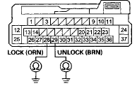
11. Check for continuity between door multiplex control unit 37P connector terminals No. 28, No. 29 and body ground individually.
DOOR MULTIPLEX CONTROL UNIT 37P CONNECTOR

Wire side of female terminals
Is there continuity? YES-
Repair a short to ground in the LOCK or UNLOCK wire.
NO
-Replace the power window master switch, 4-door (see page 22-305), 2-door (see page 22-306).
12. Turn the ignition switch to LOCK (0).
13. Disconnect the driver's door lock actuator 10P connector.
14. Disconnect the door multiplex control unit 37P connector.
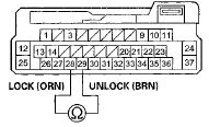
15. Check for continuity between door multiplex control unit 37P connector terminals No. 2 8 and No. 29.
DOOR MULTIPLEX CONTROL UNIT 37P CONNECTOR

Wire side of female terminals
Is there continuity? YES-
Repair a short between the LOCK and UNLOCK w i r e s . NO
-Substitute a known-good power window master switch. If the symptom goes away, replace the original power window master switch, 4-door (see page 22-305), 2-door (see page 22-306). If not, replace the driver's door lock actuator (front door latch) (see page. 20-26).
DTC B1128:
Driver's Door Lock Switch Signal Malfunction
NOTE: If you are troubleshooting multiple DTCs, be sure to follow the instructions in B-CAN System Diagnosis Test Mode A (see page 22-134).
1. Clear the DTCs with the HDS.
2. Lock and unlock the driver's door with the driver's door lock switch.
3. Check for DTCs with the HDS.
Is DTC B1128 indicated? YES
-Go to step 4.
NO-
lntermittent failure, the system is OK at this time.
Check for loose or poor connection.
4. With the driver's door lock switch in the neutral position, select DOOR LOCK from the BODY ELECTRICAL system select menu, and enter DATA LIST.
5. Check the ON/OFF information of the DRIVER'S DOOR LOCK SWITCH (LOCK) and DRIVER'S DOOR LOCK SWITCH (UNLOCK).
Are both information indicators OFF? YES
-Go to step 6.
NO
-Replace the power window master switch.
6. Operate the driver's door lock switch in the LOCK and UNLOCK position, and check the ON/OFF information of the DRIVER'S DOOR LOCK SWITCH (LOCK) and DRIVER'S DOOR LOCK SWITCH (UNLOCK).
Are both DRIVER'S DOOR LOCK SWITCH (LOCK) and DRIVER'S DOOR LOCK SWITCH (UNLOCK) information indicators ON at the same time when the door lock ~ switch is in the LOCK or UNLOCK position? YES
-Replace the power window master switch.
NO-
lntermittent failure, the system is OK at this time.
Check for loose or poor connections.
DTC B1129:
Driver's Door Lock Knob Switch Malfunction
NOTE: If you are troubleshooting multiple DTCs, be sure to follow the instructions in B-CAN System Diagnosis Test Mode A (see page 22-134).
1. Clear the DTCs with the HDS.
2. Turn the ignition switch to LOCK (0) and then back to ON (II).
3. Operate the driver's door lock knob switch several times.
4. Check for DTCs with the HDS.
Is DTC B1129 indicated? YES
-Go to step 5.
NO
-lntermittent failure, the driver's door lock knob switch system is OK at this time. Check for loose or poor connections.
5. Select KEYLESS TRANSMITTER from the BODY ELECTRICAL menu, and enter the DATA LIST.
6. Check the ON/OFF information of the DRIVER'S DOOR LOCK KNOB SWITCH (LOCK) and the DRIVER'S DOOR LOCK KNOB SWITCH (UNLOCK).
Is the DRIVER'S DOOR LOCK KNOB SWITCH (LOCK) information indicator ON and the DRIVER'S DOOR LOCK KNOB SWITCH (UNLOCK) information indicator OFF with the driver's door lock knob switch in LOCK position, and is the DRIVER'S DOOR LOCK KNOB SWITCH (LOCK) information indicator OFF and the DRIVER'S DOOR LOCK KNOB SWITCH (UNLOCK) information indicator ON with the driver's door lock knob switch in UNLOCK position? YES
-Replace the power window master switch (see page 22-305).
NO
-Go to step 7.
7. Disconnect the driver's door lock actuator 10P connector.
8. Check the ON/OFF information of the DRIVER'S DOOR LOCK KNOB SWITCH (LOCK) and DRIVER'S DOOR LOCK KNOB SWITCH (UNLOCK) in the DATA LIST.
Are both information indicators OFF? YES
-Go to step 12.
NO
-Go to step 9.
9. Turn the ignition switch to LOCK (0).
10. Disconnect the door multiplex control unit 37P connector.
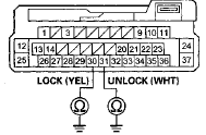
11. Check for continuity between door multiplex control unit 37P connector terminals No. 30, No. 31 and body ground individually.
DOOR MULTIPLEX CONTROL UNIT 37P CONNECTOR

Wire side of female terminals
Is there continuity? YES
-Repair a short to ground in the LOCK or UNLOCK w i r e . NO
-Replace the power window master switch (see page 22-305).
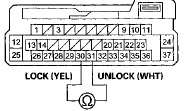
12. Check for continuity between door multiplex control unit 37P connector terminals No. 30 and No. 31.
DOOR MULTIPLEX CONTROL UNIT 37P CONNECTOR

Wire side of female terminals
Is there continuity? YES
-Repair a short between the LOCK and UNLOCK w i r e s . NO
-Check for an open or high resistance in the driver's door lock switch (LOCK) wire or the driver's door lock knob switch (UNLOCK) wire between the door multiplex control unit and the driver's door lock knob switch. If OK, replace the driver's door lock actuator.
 Circuit Diagram
...
 Symptom Troubleshooting Index
Power Door Locks/Kef less
1. Check for B-CAN DTCs. If any B-CAN DTCs are Indicated, refer to the B-CAN
System Diagnosis Test Mode A (see page
22-134) and resolve them first.
2. If the door lock ...
See also:
Playing the FM/AM Radio (Models without navigation system)
Playing the FM/AM Radio (Models without navigation system) ...
Carrier Bearing Outer Race
Replacement
Special Tools Required
-Driver Handle, 15 x 135L 07749-0010000
-Attachment, 78 x 80 mm 07NAD-PX40100
-Attachment, 72 x 75 mm 07746-0010600
NOTE:
-The bearing and the bearing outer race should be
...
A/C Condenser Replacemen
1. Recover the refrigerant with a recovery/recycling
charging station (see page 21-80).
2. Remove the front grille cover (see page 20-274).
3. Remove the intake air duct and the water separator ...
