 Honda Accord: DTC Troubleshooting
DTC 11-13:
Right-front Wheel Speed Sensor Circuit Malfunction
DTC 13-13;
Left-front Wheel Speed Sensor Circuit Malfunction
DTC 15-13:
Right-rear Wheel Speed Sensor Circuit Malfunction
DTC 17-13
: Left-rear Wheel Speed. Sensor Circuit Malfunction
1. Turn the ignition switch to ON (II).
2. Clear the DTC with the HDS.
3. Turn the ignition switch to LOCK (0), then turn it to ON (II) again.
4. Check for DTCs with the HDS.
Is DTC 11-13,13-13, 15-13, and/or 17-13 indicated? YES
-Go to step 5.
NO
-lntermittent failure, the system is OK at this time.
Check for loose terminals between the wheel speed sensor 2P connector and the VSA modulator-control unit 36P connector. Refer to intermittent failures troubleshooting (see page 19-49).
5. Turn the ignition switch to LOCK (0).
6. Disconnect the VSA modulator-control unit 36P connector (see step 3 on page 19-137).
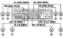
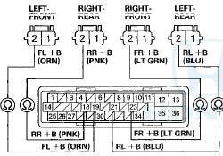
7. Check for continuity between body ground and the appropriate wheel speed sensor +B and GND terminals of the VSA moduIator-controI unit 36P connector individually (see table).
VSA MODULATOR-CONTROL UNIT 36P CONNECTOR
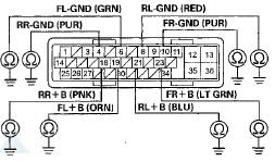
Wire side of female terminals
Is there continuity? YES
-Go to step 8.
NO
-Go to step 10.
8. Disconnect the appropriate wheel speed sensor 2P connector (see page 19-139).
9. On the sensor side, check for continuity between body ground and wheel speed sensor 2P connector terminals No. 1 and No. 2 individually.
WHEEL SPEED SENSOR 2P CONNECTOR
Is there continuity? YES
-Replace the wheel speed sensor (see page 19-139).
NO
-Repair a short to body ground in the wire between the VSA modulator-control unit and the wheel speed sensor.
10. Turn the ignition switch to ON (II).
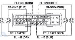
11. Measure the voltage between body ground and the appropriate wheel speed sensor +B and GND terminals of the VSA modulator-control unit 36P connector individually (see table).
VSA MODULATOR-CONTROL UNIT 36P CONNECTOR
Wire side of female terminals
Is there 0.1 V or more? YES
-Go to step 12.
NO
-Go to step 16.
12. Turn the ignition switch to LOCK (0).
13. Disconnect the appropriate wheel speed sensor 2P connector (see page 19-139).
14. Turn the ignition switch to ON (II).
15. On the sensor side, measure the voltage between body ground and wheel speed sensor 2P connector terminals No. 1 and No. 2 individually.
WHEEL SPEED SENSOR 2P CONNECTOR
Terminal side of male terminals
Is there 0.1 Vormore? YES
-Replace the wheel speed sensor (see page 19-139).
NO
-Repair a short to power in the wire between the VSA modulator-control unit and the appropriate wheel speed sensor.
16. Turn the ignition switch to LOCK (0).
17. Disconnect the appropriate wheel speed sensor 2P connector (see page 19-139).
18. Check for continuity between the appropriate VSA modulator-control unit 36P connector wheel speed sensor +B and GND terminals (see table).
VSA MODULATOR-CONTROL UNIT 36P CONNECTOR
Wire side of female terminals
Is there continuity? YES
-Repair a short in the wires between the appropriate wheel speed sensor and the VSA modulator-control unit.
NO
-Go to step 19.
19. Check for continuity between the appropriate VSA modulator-control unit 36P connector terminal and the wheel speed sensor 2P connector terminal (see table).
WHEEL SPEED SENSOR 2P CONNECTOR
Terminal side of female terminals
VSA MODULATOR-CONTROL UNIT 36P CONNECTOR
Wire side of female terminals
Is there continuity? YES
-Go to step 20.
NO
-Repair an open in the wire between the appropriate wheel speed sensor and the VSA modulator-control unit.
20. Check for continuity between the appropriate VSA modulator-control unit 36P connector terminal and the wheel speed sensor 2P connector terminal (see table).
WHEEL SPEED SENSOR 2P CONNECTOR
VSA MODULATOR-CONTROL UNIT 36P CONNECTOR
Wire side of female terminals
Is there continuity? YES
-Go to step 21.
NO
-Repair an open in the wire between the appropriate wheel speed sensor and the VSA modulator-control unit.
21. Substitute a known-good wheel speed sensor (see page 19-139).
22. Reconnect all connectors.
23. Turn the ignition switch to ON (II).
24. Clear the DTC with the HDS.
25. Turn the ignition switch to LOCK (0), then turn it to ON (II) again.
26. Check for DTCs with the HDS.
Is DTC 11-13, 13-13, 15-13, and/or 17-13 indicated? YES
-Go to step 27.
NO
-Replace the original wheel speed sensor (see page 19-139).
27. Update the VSA modulator-control unit if it does not have the latest software (see page 19-135). If the unit already has the latest softwear, substitute a knowngood VSA modulator-control unit (see page 19-136).
28. Turn the ignition switch to LOCK (0), then turn it to ON (II) again.
29. Check for DTCs with the HDS.
Is DTC 11-13,13-13, 15-13, and/or 17-13 indicated? YES-
Check for loose terminals in the VSA modulatorcontrol unit 36P connector. If the VSA modulatorcontrol unit was updated, substitute a known-good VSA modulator-control unit (see page 19-136), then retest. If the VSA modulator-control unit was substituted, go to step 1.
NO
-lf the VSA modulator-control unit was updated, troubleshooting is complete. If the VSA modulatorcontrol unit was substituted, replace the original VSA modulator-control unit (see page 19-136). If any other DTCs are indicated, go to the indicated DTCs troubleshooting.
DTC 11-14:
Right-front Wheel Speed Sensor Power Source Malfunction
DTC 13-14:
Left-front Wheel Speed Sensor Power Source Malfunction
DTC 15-14:
Right-rear Wheel Speed Sensor Power Source Malfunction
DTC 17-14:
Left-rear Wheel Speed Sensor Power Source Malfunction
1. Turn the ignition switch to ON (II).
2. Clear the DTC with the HDS.
3. Turn the ignition switch to LOCK (0), then turn it to ON (II) again.
4. Check for DTCs with the HDS.
Is DTC 11-14, 13-14, 15-14, and/or 17-14 indicated? YES-
Go to step 5.
NO
-lntermittent failure, the system is OK at this time.
Check for loose terminals between the wheel speed sensor 2P connector and the VSA modulator-control unit 36P connector. Refer to intermittent failures troubleshooting (see page 19-49).
5. Update the VSA modulator-control unit if it does not have the latest software (see page 19-135). If the unit already has the latest software, substitute a knowngood VSA modulator-control unit (see page 19-136).
6. Turn the ignition switch to ON (II).
7 Check for DTCs with the HDS.
Is DTC 11-14, 13-14, 15-14, and/or 17-14 indicated? YES
-Check for loose terminals in the VSA modulatorcontrol unit 36P connector. If the VSA modulatorcontrol unit was updated, substitute a known-good VSA modulator-control unit (see page 19-136), then retest. If the VSA modulator-control unit was substituted, go to step 1.
NO
-lf the VSA modulator-control unit was updated, troubleshooting is complete. If the VSA modulatorcontrol unit was substituted, replace the original VSA modulator-control unit (see page 19-136). If any other DTCs are indicated, go to the indicated DTCs troubleshooting.
DTC 12-11:
Right-front Wheel Speed Sensor Electrical Noise or Intermittent Interruption
DTC 16-11:
Right-rear Wheel Speed Sensor Electrical Noise or Intermittent Interruption
DTC 18-11:
Left-rear Wheel Speed Sensor Electrical Noise or Intermittent Interruption
NOTE: These DTCs may be caused by electrical interference. Check for aftermarket devices installed in the vehicle when these DTC are indicated.
1. Turn the ignition switch to ON (II).
2. Clear the DTC with the HDS.
3. Test-drive the vehicle.
NOTE: Drive the vehicle on the road, not on a lift.
4. Check for DTCs with the HDS.
Is DTC 12-11,14-11, 16-11, and/or 18-11 indicated? YES
-lf DTC 12-12,14-12,16-12, or 18-12 is indicated at the same time, do the DTC 12-12,14-12,16-12, or 18- 12 troubleshooting first (see page 19-77). If DTC 12-12,14-12,16-12, or 18-12 is not indicated, go to step 5.
NO
-lf any other DTCs are indicated, go to the indicated DTCs troubleshooting. If DTCs are not indicated, there is an intermittent failure, the system is OK at this time. Check for loose terminals between the wheel speed sensor 2P connector and the VSA modulator-control unit 36P connector. Refer to intermittent failures troubleshooting (see page 19- 49).
5. Turn the ignition switch to LOCK (0).
6. Check that the appropriate wheel speed sensor is properly mounted (see page 19-139).
Is the wheel speed sensor installation OK? YES
-Go to step 7.
NO
-Reinstall the wheel speed sensor, and check the mounting position (see page 19-139).
7. Update the VSA modulator-control unit if it does not have the latest software (see page 19-135). If the unit already has the latest software, substitute a knowngood VSA modulator-control unit (see page 19-136).
8. Test-drive the vehicle.
NOTE: Drive the vehicle on the road, not on a lift.
9. Check for DTCs with the HDS.
Is DTC 12-11, 14-11, 16-11, and/or 18-11 indicated? YES
-Check for loose terminals in the VSA modulatorcontrol unit 36P connector. If the VSA modulatorcontrol unit was updated, substitute a known-good VSA modulator-control unit (see page 19-136), then retest. If the VSA modulator-control unit was substituted, go to step 1.
NO
-lf the VSA modulator-control unit was updated, troubleshooting is complete. If the VSA modulatorcontrol unit was substituted, replace the original VSA modulator-control unit (see page 19-136). If any other DTCs are indicated, go to the indicated DTCs troubleshooting.
DTC 12-12;
Right-front Wheel Speed Sensor Short to the Other Sensor Circuit
DTC 14-12;
Left-front Wheel Speed Sensor Short to the Other Sensor Circuit
DTC 16-12:
Right-rear Wheel Speed Sensor Short to the Other Sensor Circuit
DTC 18-12:
Left-rear Wheel Speed Sensor Short to the Other Sensor Circuit
1. Turn the ignition switch to ON (II).
2. Clear the DTC with the HDS.
3. Test-drive the vehicle at 13 mph (20 km/h) or more, and go a distance of 328 ft (100 m) or more.
NOTE: Drive the vehicle on the road, not on a lift.
4. Check for DTCs with the HDS.
Is DTC 12-12,14-12, 16-12, and/or 18-12 Indicated? YES-Go to step 5.
NO-lntermittent failure, the system is OK at this time.
Check for loose terminals between the wheel speed sensor 2P connector and the VSA modulator-control unit 36P connector. Refer to intermittent failures troubleshooting (see page 19-49).H 5. Turn the ignition switch to LOCK (0).
6. Disconnect the VSA modulator-control unit 36P connector (see step 3 on page 19-137).
7. Check for continuity between the appropriate VSA modulator-control unit 36P connector wheel speed sensor GND terminals (see table).
VSA MODULATOR-CONTROL UNIT 36P CONNECTOR
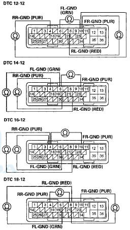
Wire side of female terminals
Is there continuity? YES
-Repair a short in the wires between the appropriate wheel speed sensor and the VSA modulator-control unit.
NO
-Go to step 8.
8. Reconnect the VSA modulator-control unit 36P connector.
9. Update the VSA modulator-control unit if it does not have the latest software (see page 19-135). If the unit already has the latest software, substitute a knowngood VSA modulator-control unit (see page 19-136).
10. Test-drive the vehicle at 13 mph (20 km/h) or more, and go a distance of 328 ft (100 m) or more.
NOTE: Drive the vehicle on the road, not on a lift.
11. Check for DTCs with the HDS.
Is DTC 12-12, 14-12, 16-12, and/or 18-12 indicated? YES
-Check for loose terminals in the VSA modulatorcontrol unit 36P connector. If the VSA modulatorcontrol unit was u n d a t e d c . h c t i t . В« t o a known-good VSA modulator-control unit (see page 19-136), then retest. If the VSA modulator-control unit was substituted, go to step 1.
NO
-lf the VSA modulator-control unit was updated, troubleshooting is complete. If the VSA modulatorcontrol unit was substituted, replace the original VSA modulator-control unit (see page 19-136). If any other DTCs are indicated, go to the indicated DTCs troubleshooting.
DTC 12-21:
Right-front Wheel Speed Sensor Installation Error
DTC 14-21:
Left-front Wheel Speed Sensor Installation Error
DTC 16-21:
Right-rear Wheel Speed Sensor Installation Error
DTC 18-21:
Left-rear Wheel Speed Sensor Installation Error
1. Test-drive the vehicle at 7 mph (10 km/h) or more.
NOTE: Drive the vehicle on the road, not on a lift.
2. Check the RIGHT FRONT, LEFT FRONT, RIGHT REAR, LEFT BEAR WHEEL SPEED in t h e VSA U A ! A L i b i with the HDS.
Are all four values the same? YES
-lntermittent failure, the system is OK at this time.
Check for loose terminals between the wheel speed sensor 2P connector and the VSA modulator-control unit 36P connector. Refer to intermittent failures troubleshooting (see page 19-49).
NO
-Go to step 3.
3. Turn the ignition switch to LOCK (0).
4. Check that the appropriate wheel speed sensor is properly mounted (see page 19-139).
Is the wheel speed sensor installation OK? YES
-Replace the appropriate wheel speed sensor (seepage 19-1S9).
NO
-Reinstall the wheel speed sensor, and check the mounting position (see page 19-139).
DTC 12-22;
Right-front Wheel Speed Sensor installation Error (19 mph (30 km/h) or More)
DTC 14-22:
Left-front Wheel Speed Sensor Installation Error (13 mph (30 km/h) or More)
DTC 16-22:
Right-rear Wheel Speed Sensor Installation Error (13 mph (30 km/h) or More)
DTC 18-22:
Left-rear Wheel Speed Sensor Installation Error (13 mph (30 km/h) or More)
1. Test-drive the vehicle between 19 mph (30 km/h) and 31 mph (50 km/h) for 70 seconds or more.' NOTE: Drive the vehicle on the road, not on a lift.
2. Check the RIGHT FRONT, LEFT FRONT, RIGHT REAR, LEFT REAR WHEEL SPEED in the VSA DATA LIST with the HDS.
Are all four values the same? YES
-lntermittent failure, the system is OK at this time.
Check for loose terminals between the wheel speed sensor 2P connector and the VSA modulator-control unit 36P connector. Refer to intermittent failures troubleshooting (see page 19-49).! NO
-Go to step 3.
3. Turn the ignition switch to LOCK (0).
4. Check that the appropriate wheel speed sensor is properly mounted (see page 19-139).
Is the wheel speed sensor installation OK? YES
-Replace the appropriate wheel speed sensor (see page 19-139).
NO
-Reinstall the wheel speed sensor, and check the mounting position (see page 19-139).
DTC 12-23:
Right-front Wheel Speed Sensor Installation Error (0 to 9 mph (0 to 15 km/h))
DTC 14-23:
Left-front Wheel Speed Sensor Installation Error (0 to 9 mph (0 to 15 km/h))
DTC 16-23:
Right-rear Wheel Speed Sensor Installation Error (0 to 9 mph (0 to 15 km/h))
DTC 18-23
: Left-rear Wheel Speed Sensor Installation Error (0 to 9 mph (0 to 15 km/h))
1. Test-drive the vehicle between 1 mph (1 km/h) and 9 mph (15 km/h).
NOTE: Drive the vehicle on the road, not on a lift.
2. Check the RIGHT FRONT, LEFT FRONT, RIGHT REAR, LEFT REAR WHEEL SPEED in the VSA DATA LIST with the HDS.
Are all four values the same? YES
-lntermittent failure, the system is OK at this time.
Check for loose terminals between the wheel speed sensor 2P connector and the VSA modulator-control unit 36P connector. Refer to intermittent failures troubleshooting (see page 19-43).
NO
-Gq to step 3.
3. Turn the ignition switch to LOCK (0).
4. Check that the appropriate wheel speed sensor is properly mounted (see page 19-139).
Is the wheel speed sensor installation OK? YES
-Replace the appropriate wheel speed sensor (see page 19-139).
NO
-Reinstall the wheel speed sensor, and check the mounting position (see page 19-139).
DTC 21-11:
Right-front Magnetic Encoder (Wheel Bearing) Malfunction (Pulse Missing)
DTC 22-11:
Left-front Magnetic Encoder (Wheel Bearing) Malfunction (Pulse Missing)
DTC 23-11:
Right-rear Magnetic Encoder (Wheel Bearing) Malfunction (Pulse Missing)
DTC 24-11:
Left-rear Magnetic Encoder (Wheel Bearing) Malfunction (Pulse Missing)
1. Turn the ignition switch to ON (II).
2. Clear the DTC with the HDS.
3. Test-drive the vehicle at 13 mph (20 km/h) or more, or.J go z dictor.co of 328 ft (100 m) or more.
NOTE: Drive the vehicle on the road, not on a lift.
4. Check for DTCs with the HDS.
Is DTC 21-11,22-11,23-11, and/or 24-11 indicated? YES
-Go to step 5.
NO
-lntermittent failure, the system is OK at this time.
Check for loose terminals between the wheel speed sensor 2P connector and the VSA modulator-control unit 36P connector. Refer to intermittent failures troubleshooting (see page 19-49) 5. Turn the ignition switch to LOCK (0).
6. Inspect the appropriate magnetic encoder for damage, debris, and correct installation.
Is the magnetic encoder surface OK? YES
-Remove the debris from the magnetic encoder, or replace the wheel bearing (front) or the hub bearing unit (rear): - Front: Replace the wheel bearing (see page 18-14).
- Rear: Replace the hub bearing unit (see page 18-39).
NO
-Clean dust or dirt from the appropriate magnetic encoder surface on the wheel bearing or the hub bearing unit, then go to step 1 and recheck. If the DTC is still present, replace the appropriate wheel bearing or hub bearing unit.
DTC 25-12:
Yaw Rate Sensor internal Circuit Malfunction (Open, Short)
DTC 25-13:
Yaw Rate Sensor Internal Circuit Malfunction
DTC 25-18:
Yaw Rate-Lateral Acceleration Sensor Internal Circuit Malfunction
DTC 26-12:
Lateral Acceleration Sensor Internal Circuit Malfunction (Open, Short)
DTC 26-13:
Lateral Acceleration Sensor Internal Circuit Malfunction
1. Turn the ignition switch to ON (II).
2. Clear the DTC with the HDS.
3. Turn the ignition switch to LOCK (0), then turn it to ON (II) again.
4. Check for DTCs with the HDS.
Is DTC 25-12, 25-13, 25-18, 26-12, or 26-13 indicated? YES-
Replace the yaw rate-lateral acceleration sensor (seepage 19-133).
NO
-lntermittent failure, the system is OK at this time.
DTC 25-17:
Yaw Rate-Lateral Acceleration Sensor Power Source Voltage Malfunction
1. Turn the ignition switch to ON (II).
2. Clear the DTC with the HDS.
3. Turn the ignition switch to LOCK (0), then turn it to ON (II) again.
4. Check for DTCs with the HDS.
Is DTC 25-17 indicated? YES
-lf DTC 61-01,61-21, 61-22, 61-23, and/or 62-21 is indicated at the same time, check the battery performance (see page 22-90), and do the alternator and regulator circuit troubleshooting first (see page 4-27). If DTC 61-01, 61-21, 61-22,61-23, and/or 62-21 is not indicated at the same time, replace the yaw rate-lateral acceleration sensor (see page 19-133).
NO
-lntermittent failure, the system is OK at this time.
DTC 25-21:
Yaw Rate Sensor Neutral Position Malfunction
DTC 25-23:
Yaw Rate Sensor Circuit Intermittent Interruption
1. Turn the ignition switch to ON (II).
2. Clear the DTC with the HDS.
3. Turn the ignition switch to LOCK (0), then turn it to ON (II) again.
4. Wait 60 seconds or more.
5. Check for DTCs with the HDS.
Is DTC 25-21 or 25-23 indicated? YES
-Rfepiaoe me yaw rate-laterai acceleration sensor (see page 19-133).
NO
-lntermittent failure, the system is OK at this time.
DTC 25-22:
Yaw Rate Sensor Stuck
1. Turn the ignition switch to ON (II).
2. Clear the DTC with the HDS.
3. Test-drive the vehicle at 7 mph (10 km/h) or more.
NOTE: Drive the vehicle on the road, not on a lift.
4. Check for DTCs with the HDS.
Is DTC 25-22 indicated? YES
-Go to step 5.
NO
-lf any other DTCs are indicated, go to the indicated DTCs troubleshooting. If DTCs are not indicated, intermittent failure, the system is OK at this time.
5. Test-drive the vehicle. Check the YAW RATE S in the VSA DATA LIST with the HDS while driving in corners.
Does the indicated value change? YES
-lntermittent failure, the system is OK at this time.
NO-
Replace the yaw rate-lateral acceleration sensor (see page 19-133).
DTC 25-24:
Yaw Rate Sensor Gain Low
DTC 25-25:
Yaw Rate Sensor Gain High
DTC 26-24:
Lateral Acceleration Sensor Gain Low
DTC 26-25:
Lateral Acceleration Sensor Gain High
1. Turn the ignition switch to ON (II).
2. Clear the DTC with the HDS.
3. Test-drive the vehicle at 10 mph (15 km/h) or more.
NOTE: Drive the vehicle on the road, not on a lift.
4. Check for DTCs with the HDS.
Is DTC 25-24, 25-25, 26-24, or 26-25 indicated? YES-Replace the yaw rate-lateral acceleration sensor (see page 19-133).
NO-lntermittent failure, the system is OK at this time.
DTC 26-21:
Lateral Acceleration Sensor Neutral Position Malfunction
DTC 26-23:
Lateral Acceleration Sensor Circuit Intermittent Interruption
NOTE: While doing this troubleshooting, avoid vibration or shaking of the vehicle.
1. Park the vehicle on a flat and level surface.
2. Turn the ignition switch to ON (II).
3. Clear the DTC with the HDS.
4. Turn the ignition switch to LOCK (0), then turn it to ON (II) again.
5. Wait 60 seconds or more.
6. Check for DTCs with the HDS.
Is DTC 26-21 or 26-23 indicated? YES
-Replace the yaw rate-lateral acceleration sensor (see page 19-133).
NO
-lntermittent failure, the system is OK at this time
PTC 26-22:
Lateral Acceleration Sensor Stuck
1. Turn the ignition switch to ON (II).
2. Clear the DTC with the HDS.
3. Test-drive the vehicle at 7 mph (10 km/h) or more.
NOTE: Drive the vehicle on the road, not on a lift.
4. Check for DTCs with the HDS.
Is DTC 26-22 indicated? YES
-Go to step 5.
NO
- l f any other DTCs are indicated, go to the indicated DTCs troubleshooting. If DTCs are not indicated, intermittent failure, the system is OK at this time.
5. Test-drive the vehicle. Check the LATERAL ACCELERATION SENSOR in the VSA DATA LIST with the HDS while driving around corners.
Does the indicated value change? YES
-lntermittent failure, the system is OK at this time.
NO
-Replace the yaw rate-lateral acceleration sensor (see page 19-133).
DTC 27-11:
Steering Angle Sensor DIAG Signal Error (Initial)
DTC 27-26:
Steering Angle Sensor DIAG Signal Error (Main)
1. Turn the ignition switch to ON (II).
2. Clear the DTC with the HDS.
3. Turn the ignition switch to LOCK (0), then turn it to ON (II) again.
4. Check for DTCs with the HDS.
Is DTC 27-11 or 27-26 indicated? YES
-Go to step 5.
NO
- Intermittent failure, t h e system is OK at this time.
Check for loose terminals between the steering angle sensor 5P connector and the VSA modulator-control unit 36P connector. Refer to intermittent failures troubleshooting (see page 19-49).
5. Turn the ignition switch to LOCK (0).
6. Disconnect the steering angle sensor 5P connector (see page 19-132).
7. Disconnect the VSA modulator-control unit 36P connector (see step 3 on page 19-137).
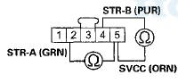
8. Check for continuity between body ground and steering angle sensor 5P connector terminals No. 2, No. 3, No. 4, and No. 5 individually.
STEERING ANGLE SENSOR BP CONNECTOR
Wire side of female terminals
Is there continuity? YES
-Repair a short to body ground in the wire between the steering angle sensor and the VSA modulator-control unit.
NO
-Go to step 9.
9. Check for continuity between the VSA modulatorcontrol unit 36P connector terminal and the steering angle sensor 5P connector terminal individually (see table).
STEERING ANGLE SENSOR BP CONNECTOR
Wire side of female terminals
VSA MODULATOR-CONTROL UNIT 36P CONNECTOR
Wire side of female terminals
Is there continuity? YES
-Go to step 10.
NO
-Repair an open in the wire between the steering angle sensor and the VSA modulator-control unit.
10. Substitute a known-good steering angle sensor (see page 19-132).
11. Reconnect all connectors.
12. Turn the ignition switch to ON (II).
13. Clear the DTC with the HDS.
14. Turn the ignition switch to LOCK (0), then turn it to ON (II) again.
15. Check for DTCs with the HDS.
Is DTC 27-11 or 27-26 indicated? YES
-Go to step 16.
NO
-Replace the original steering angle sensor (see page 19-132).
16. Update the VSA modulator-control unit if it does not have the latest software (see page 19-135). If the unit already has the latest software, substitute a knowngood VSA modulator-control unit (see page 19-136).
17. Turn the ignition switch to LOCK (0), then turn it to ON (II) again.
18. Check for DTCs with the HDS.
Is DTC 27-11 or 27-26 indicated? YES
-Check for loose terminals in the VSA modulatorcontrol unit 36P connector. If the VSA modulatorcontrol unit was updated, substitute a known-good VSA modulator-control unit (see page 19-136), then retest. If the VSA modulator-control unit was substituted, go to step 1.
NO
-lf the VSA modulator-control unit was updated, troubleshooting is complete. If the VSA modulatorcontrol unit was substituted, replace the original VSA modulator-control unit (see page 19-136). If any other DTCs are indicated, go to the indicated DTCs troubleshooting.
DTC 27-21:
Steering Angle Sensor Stuck Neutral Position
DTC 27-22:
Steering Angle Sensor Stuck Offset Position
1. Turn the ignition switch to ON (II).
2. Turn the steering wheel left and right 90 degrees or more. Check the STEERING ANGLE in the VSA DATA LIST with the HDS.
Is there +90 ° or more, and —90 ° or less? YES
-lntermittent failure, the system is OK at this time.
Check for loose terminals between the steering angle sensor 5P connector and the VSA modulator-control NO
-Go to step 3.
3. Turn the ignition switch to LOCK (0).
4. Disconnect the steering angle sensor 5P connector (see page 19-132).
5. Disconnect the VSA modulator-control unit 36P connector (see step 3 on page 19-137).
6. Turn the ignition switch to ON (II).
7. Measure the voltage between body ground and steering angle sensor 5P connector terminals No. 2, No. 3, and No. 4 individually.
STEERING ANGLE SENSOR 5P CONNECTOR
Wire side of female terminals
Is there 0.1 Vor more? YES
-Repair a short to power in the wire between the steering angle sensor and the VSA modulator-control unit.
NO
-Replace the steering angle sensor (see page 19-132).
DTC 27-23
: Steering Angle Sensor Counter Malfunction
1. Turn the ignition switch to ON (II).
2. Clear the DTC with the HDS.
3. Turn the ignition switch to LOCK (0).
4. Start the engine.
5. Turn the steering wheel from lock to lock several times.
6. Check for DTCs with the HDS.
Is DTC 27-23 indicated? YES-
Go to step 7.
NO
-lntermittent failure, the system is OK at this time.
Check for loose terminals between the steering angle sensor 5P connector and the VSA modulator-control unit 36P connector. Refer to intermittent failures troubleshooting (see page 19-49).
7. Turn the ignition switch to LOCK (0).
8. Disconnect the steering angle sensor 5P connector (see page 19-132).
9. Disconnect the VSA modulator-control unit 36P connector (see step 3 on page 19-137).
10. Check for continuity between steering angle sensor 5P connector terminals No. 2 and No. 4.
STEERING ANGLE SENSOR 5P CONNECTOR
Wire side of female terminals
Is there continuity? YES
- Ropair a short in the wiros between the steering angle sensor and the VSA modulator-control unit.B NO-Go to step 11.
11. Check for continuity between steering angle sensor 5P connector terminals No. 5 and No. 2, and No. 5 and No. 4 individually.
STEERING ANGLE SENSOR 5P CONNECTOR
Wire side of female terminals
Is there continuity? YES
-Repair a short in the wires between the steering angle sensor and the VSA modulator-control unit.il NO
-Go to step 12.
12. Check for continuity between steering angle sensor 5P connector terminals No. 1 and No. 2, and No. 1 and No. 4 individually.
STEERING ANGLE SENSOR 5P CONNECTOR
Wire side of female terminals
Is there continuity? YES
-Repair a short in the wires between the steering angle sensor and the VSA moduIator-controI unit.
NO
-Replace the steering angle sensor (see page 19-132).
DTC 27-24
: Steering Angle Sensor Exchange Malfunction
1. Turn the ignition switch to ON (II), and set the front wheels to the straight ahead position.
2. Turn the steering wheel one turn to the left. Check the STEERING ANGLE in the VSA DATA LIST with the HDS.
Is there about 288 degrees to 432 degrees positive? YES
-lntermittent failure, the system is OK at this time.
NO
-Replace the steering angle sensor (see page 19-132).
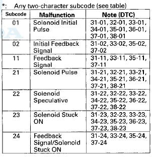
DTC 31-xx*:
ABS Right-front Inlet Solenoid Valve Malfunction
DTC 32-xx*
: ABS Right-front Outlet Solenoid Valve Malfunction
DTC 33-xx*:
ABS Left-front Inlet Solenoid Valve Malfunction
DTC 34-xx*:
ABS Left-front Outlet Solenoid Valve Malfunction
DTC 35-xx*:
ABS Right-rear Inlet Solenoid Valve Malfunction
DTC 36-xx*:
ABS Right-rear Outlet Solenoid Valve Malfunction
DTC 37-xx*:
ABS Left-rear Inlet Solenoid Valve Malfunction
DTC 38-xx*:
ABS Left-rear Outlet Solenoid Valve Malfunction
1. Turn the ignition switch to ON (li).
2. Clear the DTC with the HDS.
3. Turn the ignition switch to LOCK (0), then turn it to ON (II) again.
4. Check for DTCs with the HDS.
Is DTC 31-xx, 32-xx, 33-xx, 34-xx, 35-xx, 36-xx, 37-xx, or 38-xx indicated? YES
-Go to step 5.
NO
-lntermittent failure, the system is OK at this t i m e.
5. Update the VSA modulator-control unit if it does not have the latest software (see page 19-135). If the unit already has the latest software, substitute a knowngood VSA modulator-controi unit {see page 19-136).
6. Turn the ignition switch to LOCK (0), then turn it to ON (II) again.
7 Check for DTCs with the HDS.
Is DTC 37-xx, 32-xx, 33-xx, 34-xx, 35-xx, 36-xx, 37-xx, or 38-xx indicated? YES-
Check for loose terminals in the VSA modulatorcontrol unit 36P connector. If the VSA modulatorcontrol unit was updated, substitute a known-good VSA modulator-control unit (see page 19-136), then retest. If the VSA modulator-control unit was substituted, go to step 1.
NO
-lf the VSA modulator-control unit was updated, troubleshooting is complete. If the VSA modulatorcontrol unit was substituted, replace the original VSA modulator-control unit (see page 19-136). If any other DTCs are indicated, go to the indicated DTCs troubleshooting.
DTC 41-21
: Right-front Wheel Lock
DTC 42-21;
Left-front Wheel Lock
DTC 43-21:
Right-rear Wheel Lock
DTC 44-21:
Left-rear Wheel Lock
The DTCs may be indicated under these conditions: - The vehicle goes into a spin.
- The ABS or VSA continues to operate for a long time.
- Snow, dirt, or debris build-up on the wheel speed sensor or magnetic encoder.
- Misadjusted brake pedal position switch.
- Contaminated brake fluid.
1. Drive the vehicle until the brakes drag or until the pedal is high and hard. This can take 20 or more brake pedal applications during an extended test-drive.
2. With the engine running, raise and support the vehicle (see page 1-13), then spin the appropriate wheel by hand.
Is there brake drag? YES
-Repair the brake drag (see page 19-5).
NO
-Go to step 3.
3. Check that the appropriate wheel speed sensor is properly mounted (see page 19-139).
Is the wheel speed sensor installation OK? YES
-Go to step 4.
NO
-Reinstall the wheel speed sensor, and check the mounting position (see page 19-139).
4. Turn the ignition switch to ON (II).
5. Clear the DTC with the HDS.
6. Test-drive the vehicle at 7 mph (10 km/h) for 20 seconds or more.
NOTE: Drive the vehicle on the road, not on a lift.
7. Check for DTCs with the HDS.
Is DTC 41-21, 42-21, 43-21, and/or 44-21 Indicated? YES
-Go to step 8.
NO
-lf any other DTCs are indicated, go to the indicated DTCs troubleshooting. If DTCs are not indicated, intermittent failure, the system is OK at this time. Refer to intermittent failures troubleshooting (see page 19-49).
8. Update the VSA modulator-control unit if it does not have the latest software (see page 19-135). If the unit already has the latest software, substitute a knowngood VSA modulator-control unit (see page 19-136).
9. Test-drive the vehicle at 7 mph (10 km/h) for 20 seconds or more.
NOTE: Drive the vehicle on the road, not on a lift.
10. Check for DTCs with the HDS.
Is DTC 41-21, 42-21, 43-21, and/or 44-21 indicated? YES
-Check for loose terminals in the VSA modulatorcontrol unit 36P connector. If the VSA modulatorcontrol unit was updated, substitute a known-good VSA modulator-control unit (see page 19-136), then retest. If the VSA modulator-control unit was substituted, go to step 1.
NO
-lf the VSA modulator-control unit was updated, troubleshooting is complete. If the VSA modulatorcontrol unit was substituted, replace the original VSA modulator-control unit (see page 19-136). If any other DTCs are indicated, go to the indicated DTCs troubleshooting.
DTC 51-11
: Motor Lock
DTC 51-13:
Motor Drive Circuit Malfunction
1. Turn the ignition switch to ON (II).
2. Clear the DTC with the HDS.
3. Turn the ignition switch to LOCK (0), then turn it to ON (II) again.
4. Wait 5 seconds.
5. Operate any one of the four solenoids, as listed, in the VSA FUNCTION TEST five times with the HDS.
6. Check for DTCs with the HDS.
Is DTC 51-11 or 51-13 indicated? YES
-Go to step 7.
NO
-lntermittent failure, the system is OK at this time.
7. Update the VSA modulator-control unit if it does not have the latest software (see page 19-135). Sf the unit already has the latest software, substitute a knowngood VSA modulator-control unit (see page 19-136).
8. Turn the ignition switch to LOCK (0), then turn it to ON (II) again.
9. Wait 5 seconds.
10. Operate any one of the four solenoids, as listed, in the VSA FUNCTION TEST five times with the HDS.
11. Check for DTCs with the HDS.
Is DTC 51-11 or 51-13 indicated? YES
-Check for loose terminals in the VSA modulatorcontrol unit 36P connector. If the VSA modulatorcontrol unit was updated, substitute a known-good VSA modulator-control unit (see page 19-136), then retest. If the VSA modulator-control unit was substituted, go to step 1.
NO
-!f the VSA n-.cdulMtG.-wiiuuS unit was updated, troubleshooting is complete. If the VSA modulatorcontrol unit was substituted, replace the original VSA modulator-control unit (see page 19-136). If any other DTCs are indicated, go to the indicated DTCs troubleshooting.
DTC 51-12:
Motor Drive Circuit Malfunction
1. Turn the ignition switch to ON (II).
2. Clear the DTC with the HDS.
3. Turn the ignition switch to LOCK (0), then turn it to ON (II) again.
4. Check for DTCs with the HDS.
Is DTC 51-12 indicated? YES
-Go to step 5.
NO
-lntermittent failure, the system is OK at this time.
Check for loose terminals at the VSA modulatorcontrol unit 36P connector. Refer to intermittent failures troubleshooting (see page 13-43).
5. Turn the ignition switch to LOCK (0).
6. Check the No. 2 (30 A) fuse in the under-hood fuse/ relay box.
Is the fuse blown? YES
-Go to step7.
NO
-Reinstall the checked fuse, then go to step 14.
7. Disconnect the VSA modulator-control unit 36P connector (see step 3 on page 19-137).
8. Check for continuity between VSA modulator-control unit 36P connector terminal No. 13 and body ground.
VSA MODULATOR-CONTROL UNIT 36P CONNECTOR
Wire side of female terminals
Is there continuity? YES
-Repair a short to body ground in the wire between the No. 2 (30 A) fuse in the under-hood fuse/relay box and the VSA modulator-control unit.
NO
-lnstall a new No. 2 (30 A) fuse in the under-hood fuse/relay box, then go to step 9.
9. Reconnect the VSA modulator-control unit 36P connector.
10. Turn the ignition switch to ON (II).
11. Clear the DTC with the HDS.
12. Turn the ignition switch to LOCK (0), then turn it to ON (II) again.
13. Check for DTCs with the HDS.
Is DTC 51-12 indicated? YES-
Replace the VSA modulator-control unit (see page 19-136).
NO
-The troubleshooting is complete.
14. Disconnect the VSA modulator-control unit 36P connector (see step 3 on page 19-137).
15. Measure the voltage between VSA modulator-control unit 36P connector terminal No. 13 and body ground.
VSA MODULATOR-CONTROL UNIT 36P CONNECTOR
Wire side of female terminals
Is there battery voltage? YES
-Go to step 16.
NO
-Repair an open in the wire between the No. 2 (30 A) fuse in the under-hood fuse/relay box and the VSA modulator-control unit.
16. Reconnect the VSA modulator-control unit 36P connector.
17. Update the VSA modulator-control unit if it does not have the latest software (see page 19-135). If the unit already has the latest software, substitute a knowngood VSA modulator-control unit (see page 19-136).
18. Turn the ignition switch to LOCK (0), then turn it to ON (II) again.
19. Check for DTCs with the HDS.
Is DTC 51-12 indicated? YES
-Check for loose terminals in the VSA modulatorcontrol unit 36P connector. If the VSA modulatorcontrol unit was updated, substitute a known-good VSA modulator-control unit (see page 19-136), then retest. If the VSA modulator-control unit was substituted, go to step 1.
NO
-lf the VSA modulator-control unit was updated, troubleshooting is complete. If the VSA modulatorcontrol unit was substituted, replace the original VSA modulator-control unit (see page 19-136). If any other DTCs are indicated, go to the indicated DTCs troubleshooting.
DTC 52-12
: Motor Stuck OFF
1. Turn the ignition switch to ON (II).
2. Clear the DTC with the HDS.
3. Turn the ignition switch to LOCK (0), then turn it to ON (II) again.
4. Operate any one of the four solenoids, as listed, in the VSA FUNCTION TEST five times with the HDS.
5. Check for DTCs with the HDS.
Is DTC 52 12 Indicated?
YES
-Go to step 6.
NO
-lntermittent failure, the system is OK at this time.
6. Update the VSA modulator-control unit if it does not have the latest software (see page 19-135). If the unit already has the latest software, substitute a knowngood VSA modulator-control unit (see page 19-136).
7. Turn the ignition switch to LOCK (0), then turn it to ON (II) again.
8. Operate any one of the four solenoids, as listed, in the VSA FUNCTION TEST five times with the HDS.
9. Check for DTCs with the HDS.
Is DTC 52-12 indicated? YES
-Check for loose terminals in the VSA modulatorcontrol unit 36P connector. If the VSA modulatorcontrol unit was updated, substitute a known-good VSA modulator-control unit (see page 19-136), then retest. If the VSA modulator-control unit was substituted, go to step 1.
NO
-lf the VSA modulator-control unit was updated, troubleshooting is complete. If the VSA modulatorcontrol unit was substituted, replace the original VSA modulator-control unit (see page 19-136) If any other DTCs are indicated, go to the indicated DTCs troubleshooting.
DTC 53-01:
Motor Relay Stuck ON 1
DTC 53-12:
Motor Relay Stuck ON 2
1. Turn the ignition switch to ON (II).
2. Clear the DTC with the HDS.
3. Turn the ignition switch to LOCK (0), then turn it to ON (II) again.
4. Check for DTCs with the HDS.
Is DTC 53-01 or 53-12 indicated? YES
-Go to step 5.
NO
-lntermittent failure, the system is OK at this time.
Check for loose terminals at the VSA modulatorcontrol unit 36P connector. Refer to intermittent failures troubleshooting (see page 19-49).
5. Turn the ignition switch to LOCK (0).
6. Disconnect the VSA modulator-control unit 36P connector (see step 3 on page 19-137).
1. Check for continuity between VSA modulator-control unit 36P connector terminal No. 36 and body ground.
VSA MODULATOR-CONTROL UNIT 36P CONNECTOR
Wire side of female terminals
Is there continuity? YES
-Go to step 8.
NO
-Repair an open in the wire between the VSA modulator-control unit and body ground (G202).
8. Reconnect the VSA modulator-control unit 36P connector, 9. Update the VSA modulator-control unit if it does not have the latest software (see page 19-135). If the unit already has the latest software, substitute a knowngood VSA modulator-control unit (see page 19-136).
10. Turn the ignition switch to LOCK (0), then turn it to ON (II) again.
11. Check for DTCs with the HDS.
Is DTC 53-01 or 53-12 indicated? YES
-Check for loose terminals in the VSA modulatorcontrol unit 36P connector. If the VSA modulatorcontrol unit was updated, substitute a known-good VSA modulator-control unit (see page 19-136), then retest If M I O VGA modulator-control unit was substituted, go to step 1.
NO
—If the VSA modulator-control unit was updated, troubleshooting is complete. If the VSA modulatorcontrol unit was substituted, replace the original VSA modulator-control unit (see page 19-136). If any other DTCs are indicated, go to the indicated DTCs troubleshooting.
DTC 54-03:
Fail-safe Relay 1 Stuck ON
DTC 54-04:
Fail-safe Relay 1 Stuck OFF (Initial
DTC 54-21:
Fail-safe Relay 1 Stuck OFF (Main
1. Turn the ignition switch to ON (II).
2. Clear the DTC with the HDS.
3. Turn the ignition switch to LOCK (0), then turn it to ON (II) again.
4. Check for DTCs with the HDS.
Is DTC 54-03, 54-04, or 54-21 indicated? YES
-Go to step 5.
NO
-lntermittent failure, the system Is OK at this time.
5. Turn the ignition switch to LOCK (0).
6. Check the No. 2 (40 A) fuse in the under-hood fuse/ relay box.
Is the fuse blown? YES
-Go to step 7.
NO
-Reinstall the checked fuse, then go to step 14.
7. Disconnect the VSA modulator-control unit 36P connector (see step 3 on page 19-137).
8. Check for continuity between VSA modulator-control unit 36P connector terminal No. 12 and body ground.
VSA MODULATOR-CONTROL UNIT 36P CONNECTOR
Wire side of female terminals
Is there continuity? YES
-Repair a short to body ground in the wire between the No. 2 (40 A) fuse in the under-hood fuse/relay box and the VSA modulator-control unit.
NO
-lnstall a new No. 2 (40 A) fuse in the under-hood fuse/relay box, then go to step 9.
9. Reconnect the VSA modulator-control unit 36P connector.
10. Turn the ignition switch to ON (II).
11. Clear the DTC with the HDS.
12. Turn the ignition switch to LOCK (0), then turn it to ON (II) again.
13. Check for DTCs with the HDS.
Is DTC 54-03, 54-04, or 54-21 indicated? YES
-Replace the VSA modulator-control unit (see page 19-136).
NO
-The troubleshooting is complete.
14. Update the VSA modulator-control unit if it does not have the latest software (see page 19-135). If the unit already has the latest software, substitute a knowngood VSA modulator-control unit (see page 19-136).
15. Turn the ignition switch to LOCK (0), then turn it to ON (II) again.
16. Check for DTCs with the HDS.
Is DTC 54-03, 54-04, or 54-21 indicated? YES
-Check for loose terminals in the VSA modulatorcontrol unit 36P connector. If the VSA modulatorcontrol unit was updated, substitute a known-good VSA modulator-control unit (see page 19-136), then retest. If the VSA modulator-control unit was substituted, go to step 1.
NO
-lf the VSA modulator-control unit was updated, troubleshooting is complete. If the VSA modulatorcontrol unit was substituted, replace the original VSA modulator-control unit (see page 19-136). If any other DTCs are indicated, go to the indicated DTCs troubleshooting.
DTC 56-01:
Initial VIG FET Stuck OFF (Initial)
DTC 56-02:
Initial VIG FET Stuck ON
DTC 56-11:
VIG FET Stuck OFF (Main)
1. Turn the ignition switch to ON (II).
2. Clear the DTC with the HDS.
3. Turn the ignition switch to LOCK (0), then turn it to ON (II) again.
4. Check for DTCs with the HDS.
Is DTC 56-01, 56-02, or 56-11 indicated? YES
-Go to step 5.
NO
-lntermittent failure, the system is OK at this.
5. Update the VSA modulator-control unit if it does not have the latest software (see page 19-135). If the unit already has the latest software, substitute a knowngood VSA modulator-control unit (see page 19-136).
6. Turn the ignition switch to LOCK (0), then turn it to ON (II) again.
7. Check for DTCs with the HDS.
Is DTC 56-01, 56-02, or 56-11 indicated? YES
-Check for loose terminals in the VSA modulatorcontrol unit 36P connector. If the VSA modulatorcontrol unit was updated, substitute a known-good VSA modulator-control unit (see page 19-136), then retest. If the VSA modulator-control unit was substituted, go to step 1.
NO
-lf the VSA modulator-control unit was updated, troubleshooting is complete. If the VSA modulatorcontrol unit was substituted, replace the original VSA modulator-control unit (see page 19-136). If any other DTCs are indicated, go to the indicated DTCs troubleshooting.
DTC 61-01:
VSA Modulator-control Unit Initial IG Low Voltage
DTC 61-21:
VSA Modulator-control Unit Power Source Low Voltage 1
DTC 61-22:
VSA Modulator-control Unit Power Source Low Voltage 2
DTC 61-23:
VSA Modulator-control Unit Power Source Low Voltage 3
1. Turn the ignition switch to ON (II).
2. Clear the DTC with the HDS.
3. Turn the ignition switch to LOCK (0), then start the engine.
4. Check for DTCs with the HDS.
Is DTC 61-01, 61-21, 61-22, or 61-23 indicated? YES
-Go to step 5.
NO
-lntermittent failure, the system is OK at this time.
Check for loose terminals at the VSA modulatorcontrol unit 36P connector. Refer to intermittent failures troubleshooting (see page 19-49).Hi 5. Check and note BATTERY voltage in the VSA DATA LIST with the HDS.
6. Using a voltmeter, measure and note the voltage across the battery terminals.
NOTE: If the voltage is below 9.5 V, check the battery (see page 22-90), and troubleshoot the alternator regulator circuit (see page 4-27).
7. Compare the voltage noted in step 5 to the voltage in step 6.
Is the difference between the two voltage readings less then 3 V? YES
-lntermittent failure, the system is OK at this time.
Check for loose terminals at the VSA modulatorcontrol unit 36P connector. Refer to intermittent failures troubleshooting (see page 19-49). If the code resets after clearing, go to step 8.
NO
-Go to step 8.
8. Update the VSA modulator-control unit if it does not have the latest software (see page 19-135). If the unit already has the latest software, substitute a knowngood VSA modulator-control unit (see page 19-136).
9. Turn the ignition switch to LOCK (0), then start the engine.
10. Check for DTCs with the HDS.
Is DTC 61-01, 61-21, 61-22, or 61-23 indicated? YES
-Check for loose terminals in the VSA modulatorcontrol unit 36P connector. If the VSA modulatorcontrol unit was updated, substitute a known-good VSA modulator-control unit (see page 19-136), then retest. If the VSA modulator-control unit was substituted, go to step 1.
NO
-lf the VSA modulator-control unit was updated, troubleshooting is complete. If the VSA modulatorcontrol unit was substituted, replace the original VSA modulator-control unit (see page 19-136). If any other DTCs are indicated, go to the indicated DTCs troubleshooting.
DTC 62-21:
VSA Modulator-control Unit IG High Voltage
1. Turn the ignition switch to ON (II).
2. Clear the DTC with the HDS.
3. Turn the ignition switch to LOCK (0), then start the engine.
4. Check for DTCs with the HDS.
Is DTC 62-21 indicated? YES
-Go to step 5.
NO
-lntermittent failure, the system is OK at this time.
5. Check and note BATTERY voltage in the VSA DATA LIST with the HDS.
6. Using a voltmeter, measure and note the voltage accross the battery terminals.
NOTE: If the voltage is more than 15.1 V, troubleshoot the alternator regulator circuit (see page 4-27).
7. Compare the voltage noted in step 5 to the voltage in step 6.
Is the difference between the two voltage readings less than 3 V? YES
-lntermittent failure, the system is OK at this time.
Check for loose terminals at the VSA modulatorcontrol unit 36P connector. Refer to intermittent failures troubleshooting (see page 19-49). If the code resets after clearing, go to step 8.H NO
-Go to step 8.
8. Update the VSA modulator-control unit if it does not have the latest software (see page 19-135). If the unit already has the latest software, substitute a knowngood VSA modulator-control unit (see page 19-136).
9. Turn the ignition switch to LOCK (0), then start the engine.
10. Check for DTCs with the HDS.
Is DTC 62-21 indicated? YES
-Check for loose terminals in the VSA modulatorcontrol unit 36P connector. If the VSA modulatorcontrol unit was updated, substitute a known-good VSA modulator-control unit (see page 19-136), then retest. If the VSA modulator-control unit was substituted, go to step 1.
NO
-lf the VSA modulator-control unit was updated, troubleshooting is complete. If the VSA modulatorcontrol unit was substituted, replace the original VSA modulator-control unit (see page 19-136). If any other DTCs are indicated, go to the indicated DTCs troubleshooting.
DTC 64-11:
Steering Angle Sensor Power Circuit Low Voltage
1. Turn the ignition switch to ON (II).
2. Clear the DTC with the HDS.
3. Turn the ignition switch to LOCK (0), then turn it to ' ON (II) again.
4. Check for DTCs with the HDS.
Is DTC 64-11 indicated? YES
-Go to step 5.
NO
-lntermittent failure, the system is OK at this time.
5. Turn the ignition switch to LOCK (0).
6. Disconnect the steering angle sensor 5P connector (see page 19-132).
7. Disconnect the VSA modulator-control unit 36P connector (see step 3 on page 19-137).
8. Check for continuity between steering angle sensor 5P connector terminal No. 5 and body ground.
STEERING ANGLE SENSOR 5P CONNECTOR
Wire side of female terminals
is there continuity? YES
-Repair a short to body ground in the wire between the steering angle sensor and the VSA modulator-control unit.B NO
-Go to step 9.
9. Reconnect all connectors.
10. Update the VSA modulator-control unit if it does not have the latest software (see page 19-135). If the unit already has the latest software, substitute a knowngood VSA modulator-control unit (see page 19-136).
11. Turn the ignition switch to LOCK (0), then turn it to ON (II) again.
12 Check for DTCs with the HDS.
Is DTC 64-111ndicated? YES
-Check for loose terminals in the VSA modulatorcontrol unit 36P connector. If the VSA modulatorcontrol unit was updated, substitute a known-good VSA modulator-control unit (see page 19-136), then retest. If the VSA modulator-control unit was substituted, go to step 1.
NO
-lf the VSA modulator-control unit was updated, troubleshooting is complete. If the VSA modulatorcontrol unit was substituted, replace the original VSA modulator-control unit (see page 19-136). If any other DTCs are indicated, go to the indicated DTCs troubleshooting.
DTC 64-12:
Steering Angle Sensor Power Circuit High Voltage
1. Turn the ignition switch to ON (II).
2. Clear the DTC with the HDS.
3. Turn the ignition switch to LOCK (0), then turn it to ON (II) again.
4. Check for DTCs with the HDS.
Is DTC 64-12 Indicated? YES
-Go to step 5.
NO
-lntermittent failure, the system is OK at this time.
Check for loose terminals between the steering angle sensor 5P connector and the VSA modulator-control unit 36P connector. Refer to intermittent failures troubleshooting (see page 19-49).
5. Turn the ignition switch to LOCK (0).
6. Disconnect the steering angle sensor 5P connector (see page 19-132).
7. Disconnect the VSA modulator-control unit 36P connector (see step 3 on page 19-137).
8. Turn the ignition switch to ON (II).
9. Measure the voltage between steering angle sensor 5P connector terminal No. 5 and body ground.
STEERING ANGLE SENSOR 5P CONNECTOR
Wire side of female terminals
Is there 0.1 Vor more? YES
-Repair a short to power in the wire between the steering angle sensor and the VSA modulator-control unit.
NO
-Go to step 10.
10. Turn the ignition switch to LOCK (0).
11. Reconnect all connectors.
12. Update the VSA modulator-control unit if it does not have the latest software (see page 19-135). If the unit already has the latest software, substitute a knowngood VSA modulator-control unit (see page 19-136).
13. Turn the ignition switch to LOCK (0), then turn it to ON (II) again.
14. Check for DTCs with the HDS.
Is DTC 64-12 indicated? YES
-Check for loose terminals in the VSA modulatorcontrol unit 36P connector. If the VSA modulatorcontrol unit was updated, substitute a known-good VSA modulator-control unit (see page 19-136), then retest. If the VSA modulator-control unit was substituted, go to step 1.
NO
-lf the VSA modulator-control unit was updated, troubleshooting is complete. If the VSA modulatorcontrol unit was substituted, replace the original VSA modulator-control unit (see page 19-136). If any other DTCs are indicated, go to the indicated DTCs troubleshooting.
DTC 65-21:
Brake Fluid Level Stuck ON
NOTE: Bleeding the brake system while the ignition switch is ON can cause this DTC.
1. Check the brake fluid level in the master cylinder reservoir.
Is the brake fluid level OK? YES
-Go to step 2.
NO
-Do the brake pad inspection: Front (see page 19-13), rear (see page 19-30), check for brake fluid leaks or replace worn brake pads, then go to step 2 and recheck.
2. Turn the ignition switch to ON (II).
3. Clear the DTC with the HDS.
4. Turn the ignition switch to LOCK (0), then turn it to ON (II) again.
5. Check for DTCs with the HDS.
Is DTC 65-21 indicated? YES
-Go to step 6.
NO
-lntermittent failure, the system is OK at this t i m e .
6. Release the parking brake.
7. Turn the ignition switch to LOCK (0), then turn it to ON (II) again.
8. Check the brake system indicator in the gauge control module.
Does the indicator come on then go off? YES
-Go to step 13.
NO
-Go to step 9.
9. Check the BRAKE FLUID LEVEL SWITCH in the VSA DATA LIST with the HDS.
Does the HDS indicate the BRAKE FLUID LEVEL SWITCH as OFF? YES
-Substitute a known-good gauge control module (see page 22-351),
 Circuit Diagram
DRIVER'S UNDER-DASH FUSE/RELAY
BOX CONNECTOR P (20P)
BRAKE PEDAL POSITION
SWITCH 4P CONNECTOR
GAUGE CONTROL MODULE 32P CONNECTOR
VSA OFF SWITCH
BP CONNECTOR
YAW RATE-LATERAL
ACCELE ...
 Symptom Troubleshooting
VSA activation indicator does not go off, and
no DTCs are stored
NOTE: If the VSA modulator was replaced prior to the
activation indicator turning on, do the VSA sensor
neutral position memorizati ...
See also:
Adding Engine Oil
Unscrew and remove the engine oil
fill cap on top of the valve cover.
Pour in the oil slowly and carefully so
you do not spill any. Clean up any
spills immediately. Spilled oil could
damage ...
Mode Control Motor Replacement
1. Remove the blower unit (see page 21-65).
2. Disconnect the 7P connector (A) from the mode
control motor (B). Remove the self-tapping screws
and the mode control motor from the heater unit.
...
To Play an iPod
This audio system can operate the
audio files on the iPod with the
same controls used for the in-dash
disc changer. To play an iPod,
connect it to the USB adapter cable
in the console compar ...