 Honda Accord: Circuit Diagram
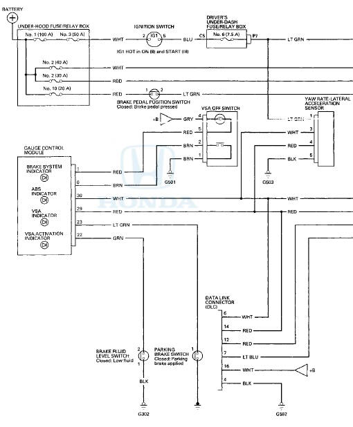
DRIVER'S UNDER-DASH FUSE/RELAY BOX CONNECTOR P (20P)
BRAKE PEDAL POSITION SWITCH 4P CONNECTOR

GAUGE CONTROL MODULE 32P CONNECTOR
VSA OFF SWITCH BP CONNECTOR

YAW RATE-LATERAL ACCELERATION SENSOR" 5P CONNECTOR

BRAKE FLUID 'LEVEL SWITCH 2P CONNECTOR'

PARKING BRAKE SWITCH 1P CONNECTOR

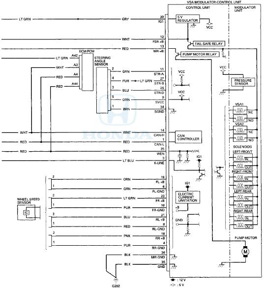
STEERING ANGLE SENSOR 5P CONNECTOR

WHEEL SPEED SENSOR 2P CONNECTOR

VSA MODULATOR-CONTROL UNIT 36P CONNECTOR
Wire side of female terminals
ECM/PCM CONNECTOR A (49P)
DATA LINK CONNECTOR (DLC)
Terminal side of female terminals
 System Description
VSA Modulator-Control Unit Inputs and Outputs for 36P Connector (Connector
Disconnected
Wire side of female terminals.
System Outline
This system i s composed of the VSA modulator-control u ...
 DTC Troubleshooting
DTC 11-13: Right-front Wheel Speed Sensor
Circuit Malfunction
DTC 13-13; Left-front Wheel Speed Sensor
Circuit Malfunction
DTC 15-13: Right-rear Wheel Speed Sensor
Circuit Malfunction
DTC 17-13: ...
See also:
Ground Distribution
Ground to Components Index
* 1 : EX-L, EX-L PZEV
*2: Except EX-L, EX-L PZEV
*3: With premium audio system
*4: With navigation system
*5: '10 model
*6: '08-09 models ...
Carrying Cargo
Your vehicle has several convenient
storage areas:
Glove box
Door and seat-back pockets
Roof-rack (if installed)
Center pockets
Console compartment
Trunk, including the rear seat
when fold ...
Blower Unit Component Replacement
Note these items when overhauling the blower unit:
• The recirculation control motor (A), the blower motor
(B), and the dust and pollen filter (C) can be replaced
without removing the blower u ...