 Honda Accord: Driveshaft Installation
NOTE: Before starting Installation, make sure the mating surfaces of the joint and the splined section are clean.
1 Apply about 5 g (0.18 oz) of moly 60 paste (P/N 08734-0001) to the contact area (A) of the outboard joint and the front wheel bearing.
NOTE: The paste helps prevent noise and vibration.
2. Install a new set ring (A) into the set ring groove (B) of the left driveshaft inboard joint.
3. Install a new set ring (A) into the set ring groove (B) of the intermediate shaft.
4. Apply 0.5—1.0 g (0.02-0.04 oz) of super high temp urea grease (P/N 08798-9002) to the whole splined surface (A) of the right driveshaft. After applying grease, remove the grease from the splined grooves at intervals of 2—3 splines and from the set ring groove (B) so that air can bleed from the intermediate shaft.
5, Clean the areas where the driveshaft contacts the differential thoroughly with solvent and dry then with compressed air.
NOTE: Do not wash the rubber parts with solvent.
6. Insert the inboard end (A) of the driveshaft into the differential (B) or intermediate shaft (C) until the set ring (D) locks in the groove (E).
NOTE: Insert the driveshaft horizontally to prevent damaging the oil seal.
Left
7. Install the outboard joint (A) into the front hub on the knuckle.
8. Wipe off any grease contamination from the ball joint tapered section and threads, then install the knuckle (A) onto the lower arm (B). Be careful not to damage the ball joint boot (C). Wipe off the grease before tightening the nut at the ball joint. Torque the castle nut (D) to the lower torque specification, then tighten it only far enough to align the slot with the ball joint pin hole.
NOTE: -Make sure the ball joint boot is not damaged or cracked.
-Do not align the nut by loosening it.
9. Install a new cotter pin (E) into the ball joint pin hole, and bend the cotter pin as shown.
10. Install the damper fork (A) over the driveshaft and onto the lower arm. Install the damper in the damper fork so the aligning tab (B) is aligned with the slot in the damper fork. Loosely install the damper pinch bolt (C).
11. Loosely install a new damper fork mounting bolt (D) and a new damper fork mounting nut (E).
12. Connect the front stabilizer link (A) to the lower arm, and loosely install a new flange nut (B). Hold the stabilizer link joint pin (C) using a hex wrench (D), and tighten the flange nut.
13. Place a floor jack under the lower arm, and raise the suspension to load it with the vehicle's weight.
NOTE: Do not put the floor jack under the ball joint 14. Tighten the damper pinch bolt and the damper fork mounting nut while holding the damper fork mounting bolt to the specified torque values, then remove the floor jack.
15. Apply a small amount of engine oil to the seating surface of a new spindle nut (A).
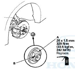
16. Install the spindle nut, then tighten it. After tightening, use a drift to stake the spindle nut shoulder (B) against the driveshaft.
17. Clean the mating surfaces of the brake disc and the wheel, then install the front wheels.
18. Turn the wheel by hand, and make sure there is no interference between the driveshaft and surrounding parts.
19. Refill the transmission with the recommended transmission fluid: -Manual transmission (see page 13-5) * Automatic transmission (see page 14-192) 20. Lower the vehicle.
21. Check the wheel alignment, and adjust it if necessary (see page 18-5).
22. Test-drive the vehicle.
 Outboard Joint Side
1. Wrap the splines on the driveshaft with vinyl tape (A)
to prevent damaging the outboard boot.
2. Install new ear clamp bands (B) and the outboard boot
onto the driveshaft, then remove the viny ...
 Intermediate Shaft Removal
1. Drain the transmission fluid. Reinstall the drain plug
using a new sealing washer:
-Manual transmission (see page 13-5)
-Automatic transmission (see page 14-192)
2. Remove the right driveshaft ...
See also:
Airbag and Tensioner Disposal
Special Tools Required
Deployment Tool 07HAZ-SG00500
Before scrapping any airbags, side airbags, side curtain
airbags, seat belt tensioners, (including those in a whole
vehicle to be scrapped), th ...
Cylinder Head Inspection for
Warpage
1. Remove the cylinder head (see page 6-76).
2. Inspect the camshaft (see page 6-84).
3. Check the cylinder head for warpage. Measure along
the edges, and three ways across the center.
- If ...
Modifying Your Vehicle
Removing parts from your vehicle,
or replacing components with
non-Honda components could
seriously affect your vehicle’s
handling, stability, and reliability.
Some examples are:
Lowering ...