 Honda Accord: Driver's Dashboard Lower Cover
Removal/Installation
Honda Accord: Driver's Dashboard Lower Cover
Removal/Installation
Special Tools Required
KTC Trim Tool Set SOJATP2014*
* Available through the Honda Tool and Equipment Program; call 888-424-6857
NOTE; - Take care not to scratch the dashboard or the related parts.
- Use the appropriate tool from the KTC trim tool set to avoid damage when removing components.
1 . Adjust the steering column to the full tilt up position.
2. Remove the driver's dashboard lower cover (A).
-1. Pull out the bottom of the cover to detach the clips (B).
-2. Pull out along the edge of the cover to detach the clips (C).
-3. Release the bottom hooks (D).
-4. Disconnect the VSA OFF switch connector (E).
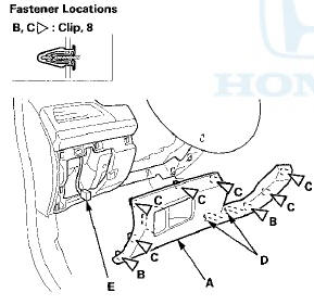
3. If necessary, remove the screws, and release the hooks (A), then remove the pocket trim (B) from the driver's dashboard lower cover (C).
4. Install the cover in the reverse order of removal, and note these items: - If the clips are damaged or stress-whitened, replace them with new ones.
- If the hooks are damaged or stress-whitened, replace the driver's dashboard lower cover with a new one.
- Make sure the VSA OFF switch connector is plugged in properly.
- Push the clips and the hooks into place securely.
 Instrument Visor Removal/Installation
Special Tools Required
KTC Trim Too! Set SOJATP2014*
*Available through the Honda Tool a n d Equipment
Program; call 888-424-6857
NOTE:
- Take care not to scratch the dashboard or the related
pa ...
 Driver's Outer Dashboard Trim
Removal/Installation
Driver's Outer Dashboard Trim
Removal/Installation
Special Tools Required
KTC Trim Tool Set SOJATP2014*
*Available through the Honda Tool and
Equipment
Program; call 888-424-6857
NOTE:
- Take care not to scratch the dashboard or the related
pa ...
See also:
Disc Repeat
To replay the current disc
continuously, select DISC REPEAT,
and press ENTER on the interface
selector. As a reminder, you will see
REPEAT next to DISC on the screen.
To turn this feature off ...
Playing Hard Disc Drive (HDD) Audio
The Hard Disc Drive (HDD) Audio function plays tracks from music CDs that
have
been recorded onto the built-in HDD. You can arrange the tracks in playlists or
play
the tracks using various sea ...
DTC Troubleshooting Index
HandsFreeLink Control Unit
...