 Honda Accord: Countershaft Assembly Clearance Inspection
tightened to the specified torque (see page 13-46).
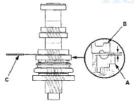
1. Measure the clearance between 1st gear (A) and the 1st gear distance collar (B) with a feeler gauge (C).
- If the clearance exceeds the service limit, go to step 2.
- If the clearance is within the service limit, go to step 4.
Standard: 0.06-0.16 mm (0.002-0.006 in)
Service Limit: 0.25 mm (0.010 in)
2. Measure the length of the 1st gear distance collar as shown.
- If the length is not within the standard, replace the 1st gear distance collar.
- If the length is within the standard, go to step 3.
Standard: 23.03-23.08 mm (0.907-0.909 in)
3. Measure the thickness of 1 st gear.
- If the thickness is less than the service limit, replace 1st gear. * - If the thickness is within the service limit, replace the 1st/2nd synchro hub and the reverse gear as a set.
Standard: 22.92~22.97 mm (0.902-0.904 In)
Service Limit: 22.87 mm (0.900 in)
4. Measure the clearance between 2nd gear (A) and 3rd gear (B) with a feeler gauge (C). If the clearance exceeds the service limit, go to step 5.
Standard: 0.06-0.16 mm f i . i i 2 - i . i i 6 in)
Service Limit: 0.25 mm (0.010 in)
5. Measure the length of the 2nd gear distance collar.
- If the length is not within the standard, replace the 2nd gear distance collar.
- If the length is within the standard, go to step 6.
Standard: 28.03-28.08 mm (1.104-1.106 in)
6. Measure the thickness of 2nd gear.
- If the thickness is less than the service limit, replace 2nd gear.
- If the thickness is within the service limit, replace the 1st/2nd synchro hub and reverse gear a s a set.
Standard: 27.92-27.97 mm (1.099-1.101 in)
Service Limit: 27.87 mm (1.097 in)
 Mainshaft Reassembly
Exploded View
*: The components of the double cone synchro assembly.
Special Tools Required
- Driver Handle, 40 mm I.D. 07746-0030100
-СћBearing Driver Attachment, 30 mm
07746-0030300
NOTE: ...
 Countershaft Disassembly
NOTE: Refer to the Exploded View in the Countershaft
Reassembly, as needed, when removing components
pressed onto the countershaft (see page 13-46).
1. Securely clamp the countershaft assembly In ...
See also:
Driver's Dashboard Lower Cover
Removal/Installation
Special Tools Required
KTC Trim Tool Set SOJATP2014*
* Available through the Honda Tool and
Equipment
Program; call 888-424-6857
NOTE;
- Take care not to scratch the dashboard or the related
p ...
Accessory Power Socket Trim
Removal/Installation
Special Tools Required
KTC Trim Tool Set SOJATP2014*
*Available through the Honda Tool and
Equipment
Program; call 888-424-6857
NOTE:
- Take care not to scratch the console.
- Use the approp ...
Instruments and Controls
This section gives information about
the controls and displays that
contribute to the daily operation of
your vehicle. All the essential
controls are within easy reach. ...