 Honda Accord: Valve Body and ATF Strainer Removal
1. Remove the ATF feed pipes (A) and the ATF joint pipes (B).
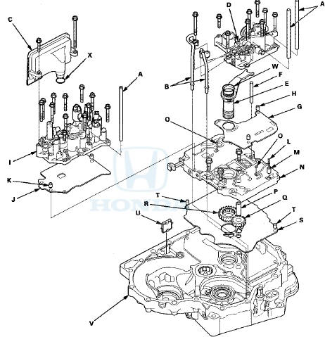
2. Remove the ATF strainer (C) (two bolts).
3. Remove the regulator valve body (D) (eight bolts).
4. Remove the stator shaft (E) and the stator shaft stop (F), then remove the regulator separator plate (G) and the two dowel pins (H).
5. Remove the servo body (I) (12 bolts), then remove the servo separator plate (J) and the two dowel pins (K).
6. Remove the cooler check valve spring (L) and the cooler check valve (M), then remove the main valve body (N) (three bolts). Do not let the two check balls (O) fall out, and do not use a magnet to remove the check balls, it may magnetize them.
7. Remove the ATF pump driven gear shaft (P), then remove the ATF pump driven gear (Q) and the ATF pump drive gear (R).
8. Remove the main separator plate (S) and the two dowel pins (T).
9. Remove the ATF magnet (U), clean and reinstall it in the torque converter housing (V).
10. Clean the inlet opening (A) of the ATF strainer (B) thoroughly with compressed air, t h e n check that it is in good condition and that the inlet opening is not clogged.
11. Test the ATF strainer by pouring clean ATF through the inlet opening, and replace it if it is clogged or damaged.
12. Remove the O-rings (W) (X) from the stator shaft and the ATF strainer. Install new ones when installing the valve bodies.
 Valve Body
...
 Valve Body Repair
NOTE: This repair is only necessary if one or more of the
valves in a valve body do not slide smoothly in their
bores. Use this procedure to free the valves.
1. Soak a sheet of #600 abrasive pape ...
See also:
A/T Gear Position Indicator Panel Light
Harness Replacement
Type A Shift Lever
NOTE: The A/T gear position indicator panel light
harness and the park pin switch are not available
separately. Replace the A/T gear position indicator panel
light harness and t ...
Radio Theft Protection
Your vehicle’s audio system may
disable itself if it is disconnected
from electrical power for any reason.
To make it work again, you must
enter a specific five-digit code with
the preset b ...
Front Door Panel Removal/Installation
Special Tools Required
-KTC Trim Tool Set SOJATP2014*
-Trim Pad Remover Snap-on A 177A,
commercially
available
*Available through the Honda Tool and
Equipment
Program; call 888-424-6857
2-do ...