 Honda Accord: Cooling System
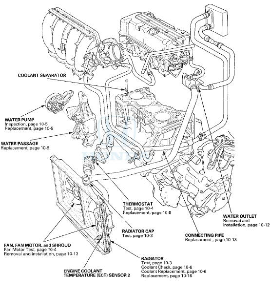
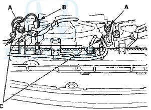
Component Location Index
Radiator Cap Test
1. Wait until the engine is cool, then carefully remove the radiator cap (A). Wet the radiator cap seal with engine coolant, then install it on a commercially available pressure tester (B).
2. Apply a pressure of 93-123 kPa (0.95-1.25 kgf/cm2,14-18 psi).
3. Check for a drop in pressure.
4. If the pressure drops, replace the radiator cap.
Radiator Test
1. Wait until the engine is cool, then carefully remove the radiator cap and fill the radiator with engine coolant to the base of the filler neck.
2. Attach a commercially available pressure tester (A) to the radiator, and apply a pressure of 93-”123 kPa (0.95-1.25 kgf/cm2,14-18 psi).
3. Inspect for engine coolant leaks and a drop in pressure.
4. Remove the tester.
5. Check for engine oil in the coolant and/or coolant in the engine oil.
6. Install the radiator cap.
Fan Motor Test
1. Disconnect the 2P connectors from the radiator fan motor and the A/C condenser fan motor.
2. Test the motor by connecting battery power to terminal No. 2 and ground to terminal No. 1.
3. If the motor fails to run or does not run smoothly, replace it (see page 10-13).
Thermostat Test
Replace the thermostat (see page 10-8) if it is stuck in the open position at room temperature.
To test a closed thermostat.
1. Suspend the thermostat (A) in a container of water.
Do not let the thermostat and the thermometer (B) touch the bottom of the hot container.
2. Heat the water, and check the temperature with a thermometer. Check the temperature at when the thermostat first opens, then check the temperature again when the thermostat is fully open.
3. Measure the lift height of the thermostat when it is fully open. If the thermostat is not within the specification, replace it.
Standard Thermostat
Lift Height: Above 8.0 mm (0.31 in) Starts Opening: 169-176 Р’В°F (76-80 Р’В°C) Fully Open: 194Р’В°F (90Р’В°C)
Water Pump Inspection
1. Remove the drive belt (see page 4-30).
2. Turn the water pump pulley counterclockwise, and check that it turns freely and smoothly. If it does not turn smoothly, replace the water pump (see page 10-5).
NOTE: When you check the water pump, you may see a small amount of "weeping" from the bleed holes (A). This is normal.
3. Install the drive belt (see page 4-30).
Water Pump Replacement
1. Remove the drive belt (see page 4-30).
2. Drain the engine coolant (see page 10-6).
3. Remove the tensioner pulley (see page 4-32).
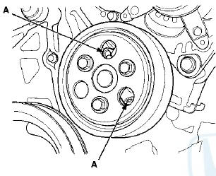
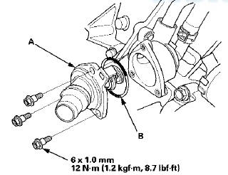
4. Remove the water pump pulley (A).
5. Remove the six bolts securing the water pump, then remove the water pump (B).
6. Inspect and clean the O-ring groove and the mating surface of the water passage.
7. Install the water pump with a new O-ring (C) and the water pump pulley.
8. Clean up any spilled engine coolant.
9. Install the tensioner pulley (see page 4-32).
10. Install the drive belt (see page 4-30).
11. Refill the radiator with engine coolant, and bleed the air from the cooling system (see step 5 on page 10-6).
Coolant Check
1. Check the coolant level in the coolant reservoir. Make sure it is between the MAX mark (A) and the MIN mark(B).
2. If the coolant level in the coolant reservoir is at or below the MIN mark, add coolant to bring it up to the MAX mark, then inspect the cooling system for leaks.
Coolant Replacement
1. Wait until the engine is cool, then carefully remove the radiator cap.
2. Loosen the drain plug (A), and drain the coolant.
3. After the coolant has drained, tighten the radiator drain plug securely.
4. Remove, drain, and reinstall the coolant reservoir.
5. Fill the coolant reservoir to the MAX mark (A) with Honda Long Life Antifreeze/Coolant Type 2.
6. Pour Honda Long Life Antifreeze/Coolant Type 2 into the radiator up to the base of the filler neck.
NOTE: - Always use Honda Long Life Antifreeze/Coolant Type 2. Using a non-Honda coolant can result in corrosion, causing the cooling system to malfunction or fail.
- Honda Long Life Antifreeze/Coolant Type 2 is a mixture of 50 % antifreeze and 50 % water. Do not add water.
- If the vehicle is regularly driven in very low temperatures (under - 3 1 Р’В°F, - 3 5 Р’В°C) a 60 % concentration of coolant should be used. To accomplish this, pour 1.6 L (0.4 US gal) of Honda Extreme Cold Weather Antifreeze/Coolant Type 2 into the radiator first, then add Honda Long Life antifreeze/Coolant Type 2 until the radiator is full.
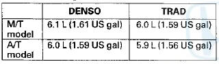
Engine Coolant Refill Capacities (Including the coolant reservoir capacity of 0.68 L (0.180 US gal))
At Coolant Change:
After Engine Overhaul ('08-09 models):
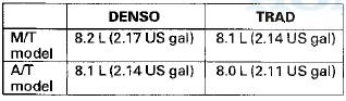
After Engine Overhaul ('10 model):
7. Loosely install the radiator cap.
8. Start the engine, and let it run until it warms up (the radiator fan comes on at least twice).
9. Turn off the engine. Check the level in the radiator, and add Honda Long Life Antifreeze/Coolant Type 2, if needed.
10. Put the radiator cap securely, then start the engine again, and check for leaks.
11. Clean up any spilled engine coolant.
12. If the maintenance minder required engine coolant replacement, reset the maintenance minder (see page 3-6), and this procedure is complete. If the maintenance minder did not require engine coolant replacement, go to step 13.
13. Turn the ignition switch to LOCK (0).
14. Connect the Honda Diagnostic System (HDS) to the data link connector (DLC) (see step 2 on page 11-3).
15. Turn the ignition switch to ON (II).
16. Make sure the HDS communicates with the vehicle and the engine control module (ECM)/powertrain control module (PCM). If it does not communicate, troubleshoot the DLC circuit (see page 11-181).
17. Select GAUGES in the BODY ELECTRICAL with the HDS.
18. Select ADJUSTMENT in the GAUGES with the HDS.
19. Select MAINTENANCE MINDER in the ADJUSTMENT ' with the HDS.
20. Select RESET in the MAINTENANCE MINDER with the HDS.
21. Select MAINTENANCE SUB ITEM 5 RESET with the HDS.
Thermostat Replacement
1. Drain the engine coolant (see page 10-6).
2. Clean any dirt off the quick connector (A), the thermostat cover, and the lower radiator hose.
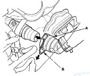
3. Pull out the lock (B) by hand, then wiggle the quick connector loose, and remove it from the thermostat cover. Do not use any tools to remove the quick connector.
4. Remove the thermostat assembly (A).
5. Install a new thermostat with a new O-ring (B).
6. Check the quick connector (A) and the set ring (B) for cracks or damage. If the connector and/or the set ring are cracked or damaged, replace the connector.
7. Wake sure the set ring Is in plauw inside the qyick connector. If the set ring is off the connector, replace the quick connector.
8. Replace a new O-ring (C) in the quick connector.
9. Check the lock (D). If the lock is damaged or deformed, replace it. When installing the new lock to the connector, push it straight down along the groove.
10. Clean the connecting surface of the thermostat cover (E), then apply clean engine coolant around the connecting surface.
11. Push the lock (A) down, then push the quick connector (B) onto the thermostat cover until you hear it click.
12. Refill the radiator with engine coolant, and bleed the air from the cooling system (see step 5 on page 10-6).
13. Clean up any spilled engine coolant.
Water Passage Replacement
1. Drain the engine coolant (see page 10-6).
2. Remove the splash shield (see step 25 on page 5-5).
3. Clean any dirt off the quick connector (A), the thermostat cover, and the lower radiator hose.
4. Pull out the lock (B) by hand, then wiggle the quick connector loose, and remove it from the thermostat cover. Do not use any tools to remove the quick connector.
5. Remove the A/C compressor without disconnecting the A/C hoses. Take care not to bend the hose excessively (see step 50 on page 5-9).
6. Remove the alternator (see page 4-32).
7. Remove the drive belt auto-tensioner (see page 4-31).
8. Remove the intake manifold (see page 9-4).
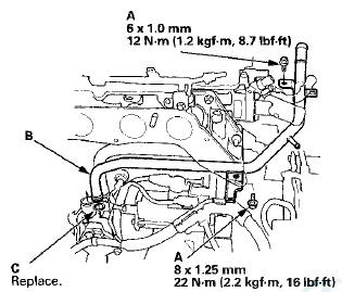
9. Remove the connecting pipe mounting bolts (A) securing the connecting pipe (B).
10. Remove the connecting pipe and disconnect the water bypass hose (C) and the positive crankcase ventilation (PCV) hose (D).
11. Remove the water passage (A).
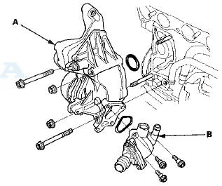
12. Remove the thermostat housing (B).
13. Remove the water pump (see page 10-5).
14. Install the water pump (see page 10-5).
15. Install the thermostat housing (A) with a new O-ring (B).
16. Clean and dry the water passage mating surfaces.
17. Apply liquid gasket, P/N 08717-0004, 08718-0003, or 08718-0009 to the engine block mating surface of the water passage, and to the inside of the threaded bolt holes. Install the component within 5 minutes of applying the liquid gasket.
NOTE: - Apply a 3 mm (0.12 in) diameter bead of liquid gasket along the broken line (A).
- If too much time has passed after applying the liquid gasket, remove the old liquid gasket and residue, then reapply new liquid gasket.
18. Install the water passage (A) with a new O-ring (B).
NOTE: - Wait at least 30 minutes before filling the engine with coolant.
- Do not run the engine for at least 3 hours after installing the water passage.
19. Connect the water bypass hose (A) and the PCV hose (B).
20. Install the connecting pipe (C) with a new O-ring (D), then tighten the connecting pipe mounting bolts (E) securing the connecting pipe.
21. Install the intake manifold (see page 9-6).
22. Install the drive belt auto-tensioner (see page 4-31).
23. Install the alternator (see page 4-33).
24. Install the A/C compressor (see step 41 on page 5-19).
25. Install the splash shield (see step 47 on page 5-20).
26. Check the quick connector (A) and the set ring (B) for cracks or damage. If the connector and/or the set ring are cracked or damaged, replace the connector.
27. Make sure the set ring is in place inside the quick connector. If the set ring is off the connector, replace the quick connector.
28. Replace the O-ring (C) in the quick connector.
29. Check the lock (D). If the lock is damaged or deformed, replace it. When installing the new lock on the connector, push it straight down along the groove.
30. Clean the connecting surface of the thermostat cover (E), then apply clean engine coolant around the connecting surface.
31. Push the lock (A) down, then push the quick connector (B) onto the thermostat cover until you hear it click.
32. Refill the radiator with engine coolant, and bleed the air from the cooling system (see step 5 on page 10-6).
33. Clean up any spilled engine coolant.
Water Outlet Removal and Installation
1. Drain the engine coolant (see page 10-6).
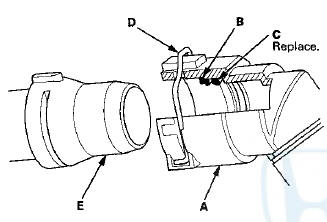
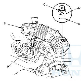
2. Disconnect the breather pipe (A), then remove the intake air duct (B).
NOTE: When tightening the screw of the hose band (C), align the edge of the hose band (D) with the mark (E) painted on the hose band. If you tighten the screw over the mark, replace the hose band.
3. Disconnect the upper radiator hose (A), the heater hose (B), and the water bypass hose (C).
4. Remove the intake manifold (see page 9-4).
5. Remove the connecting pipe mounting bolts (A), then remove the connecting pipe (B).
6. Disconnect the engine coolant temperature (ECT) sensor 1 connector (A), then remove the water outlet (B).
7. Install the water outlet with a new O-ring (C).
8. Install the other parts in the reverse order of removal.
9. Refill the radiator with engine coolant, and bleed the air from the cooling system (see step 5 on page 10-6).
10. Clean up any spilled engine coolant.
Connecting Pipe Replacement
1. Drain the engine coolant (see page 10-6).
2. Remove the intake manifold (see page 9-3).
3. Remove the connecting pipe mounting bolts (A), then remove the connecting pipe (B).
4. Install the connecting pipe with a new O-ring (C).
5. Refill the radiator with engine coolant, and bleed the airfromthe cooling system (see step 50 on page 5-9).
6. Clean up any spilled engine coolant
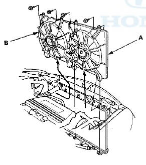
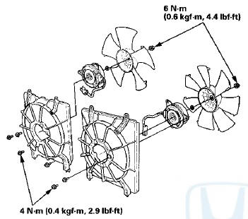
Fan, Fan Motor, and Shroud Removal and Installation
Removal
1. Do the battery removal procedure (see page 22-92).
2. Remove the harness clamps, then remove the battery base (see step 8 on page 5-3).
3. Remove the front grille cover: - 2-door (see page 20-274) - 4-door (see page 20-274) 4. Remove the water separator (A) and the intake air duct (B).
5. Remove the coolant reservoir.
6. Disconnect the fan motor connectors (A), then remove the harness clamp (B).
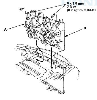
7. Remove the A/C condenser fan shroud assembly (A), then remove the radiator fan shroud assembly (B).
NOTE: Move the radiator fan shroud assembly toward the right side of the vehicle to allow enough space to lift it up and away from the A/C condenser fan shroud assembly.
8. Disassemble the fan shrouds.
Installation
1. Reassemble the fan shrouds.
2. Install the radiator fan shroud assembly (A), then install the A/C condenser fan shroud assembly (B).
3. Connect the fan motor connectors (A), then install the harness clamp (B).
4. Install the coolant reservoir.
5. install the water separator (A) and the intake air duct (B).
6. install the front grille cover: - 2-door (see page 20-274) - 4-door (see page 20-274) 7. Install the battery base, then install the harness clamps (see step 63 on page 5-22).
8. Do the battery installation procedure (see page 22-92).
Radiator Replacement
1 _ Do the battery removal procedure (see page 22-92).
2. Remove the harness clamps, then remove the battery base (see step 8 on page 5-3).
3. Remove the front grille cover: - 2-door (see page 20-274) - 4-door (see page 20-274) 4. Remove the water separator (A) and the intake air duct (B).
5. Drain the engine coolant (see page 10-6).
6. Remove the splash shield (see step 25 on page 5-5).
7. A/T model: Disconnect the automatic transmission fluid (ATF) cooler hoses (A) (see page 14-220), then plug the cooler hoses and the lines.
8. Disconnect the lower radiator hose (B) from the radiator.
9. Disconnect the fan motor connectors (A) and engine coolant temperature (ECT) sensor 2 connector (B), then remove the harness clamps (C).
11. Remove the radiator.
12. Remove the fan shroud assemblies from the radiator.
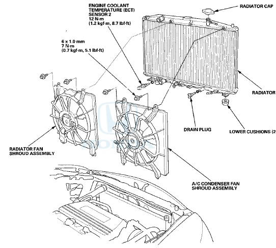
13. Install the radiator in the reverse order of removal. Make sure the upper and lower cushions (4) are set securely.
14. Do the battery installation procedure (see page 22-92).
15. Fill the radiator with engine coolant and bleed the air from the cooling system (see step 5 on page 10-6).
16. Clean up any spilled engine coolant.
 Engine Cooling
...
 Fan Controls
Component Location Index
Symptom Troubleshooting Index
'08-09 models
10 model
Circuit Diagram
'08-09 models
'10 model
Radiator Fan Circuit Troubleshooting
'08-09 models
1 ...
See also:
Side Sill Protection Tape Replacement
2-door
1. Slowly remove the old side sill protection tape.
2. Clean the body bonding surface with a shop towel
dampened in isopropyl alcohol. After cleaning, keep
oil, grease, and water from get ...
Circuit Diagram
...
Self-diagnostic Function
NOTE: Before testing, troubleshoot the multiplex integrated control unit
first, using B-CAN System Diagnosis Test Mode
A (see page 22-134).
The gauge control module has a self-diagnostic functio ...