 Honda Accord: Climate Control Switch
Removal / Installation
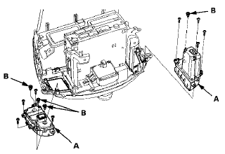
With Navigation
1 Remove the audio unit (see page 23-114).
2. Remove the self-tapping screws and the climate control switches (A). If necessary, replace the bulbs (B).

3. Install the switches in the reverse order of removal.
4. Run the self-diagnostic function to confirm that there are no problems in the system (see page 21-102).
SUPPLEMENTAL RESTRAINT SYSTEM (SRS) (if electrical maintenance is required)
The Accord SRS includes a driver's airbag in the steering wheel hub, a passenger's airbag in the dashboard above the glove box, seat belt tensioners in the front seat belt retractors, side curtain airbags in the sides of the roof, and side airbags in the front seat-backs. Information necessary to safely service the SRS is included in this Service Manual. Items marked with an asterisk (*) on the contents page include or are located near SRS components. Servicing, disassembling, or replacing these items requires special precautions and tools, and should be done by an authorized Honda dealer.
• To avoid rendering the SRS inoperative, which could lead to personal injury or death in the event of a severe frontal or side collision, all SRS service work should be done by an authorized Honda dealer.
• Improper service procedures, including incorrect removal and installation of the SRS, could lead to personal injury caused by unintentional deployment of the airbags, side airbags, and/or side curtain airbags.
• Do not bump or impact the SRS unit, front impact sensors, side impact sensors, or rear safing sensor, especially when the ignition switch is in ON (11), or for at least 3 minutes after the ignition switch is turned to LOCK (0); otherwise, the system may fail in a collision, or the airbags may deploy.
• SRS electrical connectors are identified by yellow color coding. Related components are located in the steering column, center console, dashboard, dashboard lower cover, in the dashboard above the glove box, in the front seats, in the roof side, and around the floor. Do not use electrical test equipment on these circuits.
 Climate Control Unit
Removal / Installation
With Navigation
1. Remove the passenger's dashboard undercover (see
page 20-170).
2. Disconnect the connectors (A). Loosen the bolt (B)
and remove the bolts (C) from the climate control unit (D) ...
 Body Electrical
Special Tools
General Troubleshooting Information
Tips and Precautions
Special Tools Required
Back Probe Adapter, 17 mm 07TAZ-001020A
1. Check applicable fuses in the appropriate fuse/relay
...
See also:
Intake Air Resonator
Removal / Installation
1. Do the battery removal procedure (see page 22-92).
2. Remove the air cleaner (see page 11-332).
3. Remove the battery base (A)
4. Remove the front grille cover.
- 2-door (see page 2 ...
Auxiliary Input Jack
Use the jack to connect standard audio devices.
1. Open the AUX cover.
2. Connect a standard audio device to the
input jack using a 1/8 inch (3.5 mm) stereo
miniplug.
- The audio syst ...
Status Log
If you suspect there is a immobilizer system problem, check the status log.
1. Connect the HDS to the data link connector.
2. Turn the ignition switch to ON (II).
3. On the HDS screen, at MAI ...
