 Honda Accord: Blower Unit Removal/Installation
1. Remove the glove box (see page 20-174).
2. Remove the passenger's undercover (see page 20-170).
3. Remove the right kick panel (see page 20-107).
4. Remove the dust and pollen filter assembly from the blower unit.
5. Remove the bolts (A) and the wire harness clip (B).
Then cut the plastic cross brace (C) in the glove box opening with diagonal cutters in the area shown.
Retain the plastic cross brace to be reinstalled later.
6. Disconnect these connectors (A): Passenger's under-dash fuse/relay box connector D (28P), the stereo amplifier connectors (with premium audio system), the AM/FM antenna lead, and right side wire harness connector C410 (20P). Remove the wire harness clips (B).
7. Remove the two screws, then remove the cover (A).
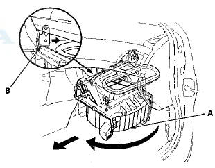
8. Disconnect the connector (B) from the blower motor and the wire harness clip (C). Remove the self-tapping screw and the mounting nut.
9. Remove the self-tapping screws, and the passenger's heater duct (A).
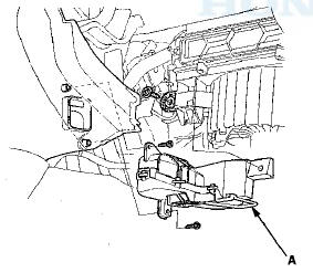
10. Disconnect the connector (A) from the recirculation control motor. Remove the mounting nuts.
11. Pull the blower unit (A) out while rotating it clockwise as shown, so that the glove box bracket (B) passes through the dust and pollen filter area.
12. Install the unit in the reverse order of removal. Make sure that there is no air leakage.
 HVAC Control Unit
Removal / Installation
HVAC Control Unit
Removal / Installation
1. Remove the audio unit (see page 23-115).'
2. Remove the self-tapping screws. If necessary, replace
the bulbs (A).
3. While holding the HVAC control unit (A), firmly press
the center of one of ...
 Blower Unit Component Replacement
Note these items when overhauling the blower unit:
• The recirculation control motor (A), the blower motor
(B), and the dust and pollen filter (C) can be replaced
without removing the blower u ...
See also:
How to Use This Manual
This manual is divided into multiple sections, The first page of
each section is marked with a black tab that lines up with its
corresponding thumb index tab on this page and the back cover.
You ...
Information Display Warning andInformation Messages
The following messages appear only on the information display.
...