 Honda Accord: Upper Arm Replacement
Special Tools Required
-Ball Joint Thread Protector, 10 mm 07AAF-SECA120
- Ball Joint Remover, 28 mm 07MAC-SL0A202
1. Raise and support the vehicle (see page 1-13).
2. Remove the front wheel.
3. Remove the front damper/spring (see page 18-31).
4. Remove the cotter pin (A) from the upper arm ball joint, then remove the castle nut (B).
5. Disconnect the upper arm ball joint from the knuckle using the ball joint thread protector and the ball joint remover (see page 18-10).
6. Remove the upper arm mounting bolts (A), then remove the upper arm (B).
7. Install the upper arm (A), and lightly tighten the new upper arm mounting bolts (B), then connect the knuckle, and lightly tighten the castle nut (C).
NOTE: - Be careful not to damage the ball joint boot when connecting the knuckle.
- Before connecting the ball joint, degrease the threaded section and the tapered portion of the ball joint pin, the ball joint connecting hole, and the threaded section and the mating surfaces of the castle nut.
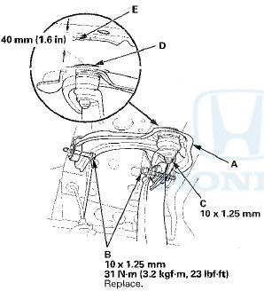
8. Place a floor jack under the lower arm, and raise the suspension until the clearance between the top (D) of the upper arm ball joint and the backside of the fender cut out point (E) is 40 mm (1.6 in), then tighten the upper arm mounting bolts to the specified torque.
NOTE: To measure the specified clearance, temporarily remove the front inner fender (see page
20-290).
9. Lower the floor jack.
10. Install the front damper/spring (see page 18-32).
11. Place the floor jack under the lower arm, and raise the suspension to load it with the vehicle's weight.
12. Tighten the castle nut (A) on the upper arm ball joint to the specified torque.
NOTE: - Torque the castle nut to the lower torque specification, then tighten it only far enough to align the slot with the ball joint pin hole. Do not align the castle nut by loosening it.
- Insert the new cotter pin (B) into the ball joint pin hole from the front to the rear of the vehicle, and bend its end as shown. Check the ball joint pin hole direction before connecting the ball joint.
13. Clean the mating surfaces of the brake disc and the inside of the wheel, then install the front wheel.
14. Check the wheel alignment, and adjust it if necessary (see page 18-5).
 Knuckle/Hub/Wheel Bearing Replacement
Exploded View
Special Tools Required
- Ball Joint Thread Protector, 14 mm
07AAE-SJAA100
- Ball Joint Thread Protector, 12 m m 07AAF-SDAA100
- Ball Joint Thread Protector, 10 m m 07AAF-SECA120
...
 Lower Arm Removal / Installation
Special Tools Required
- Ball Joint Thread Protector, 14 mm 07AAE-SJAA100
- Ball Joint Remover, 28 mm 07MAC-SL0A202
- Bushing Driver 070AF-TA0A100
- Bushing Receiver Set 070AF-TA0A220
Removal/Ins ...
See also:
Shift Lever Housing Replacement
NOTE:
- Use the appropriate tool from the KTC trim tool set to
avoid damage when removing components.
- Take care not to scratch the center console,
dashboard, and related parts.
1. Remove th ...
Pre-Owned Review: Mitsubishi Outlander (2007-2013)
Overview:
The second-generation Mitsubishi Outlander, now succeeded by the 2014 model,
has firmly transitioned into the realm of used crossovers. Positioned to rival popular
models like the Hond ...