 Honda Accord: Starter System Circuit
Troubleshooting
Honda Accord: Starter System Circuit
Troubleshooting
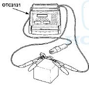
Alternator, Regulator, Battery and Starter OTC3131 * - Available through the Honda Tool and Equipment Program 888-424-6857
NOTE: - Air temperature must be within 59-”100 В°F (15-”38 В°C).
during this procedure, - After this inspection, you must reset the engine control module (ECM)/powertrain control module (PCM). Otherwise, the ECM/PCM will continue to stop the fuel injectors from operating.
- The battery must be in good condition and fully charged.
1. Connect the alternator, regulator, battery & starter tester (OTC3131) to the battery as shown.
NOTE: The probe is not used for battery testing.
2. Do the BATTERY TEST.
Does the display indicate GOOD or GOOD, LOW CHARGE? YES-The battery is OK. Go to step 3. .
NO-lf the display indicates BAD BATTERY, replace the battery, then retest. If the display indicates CHARGE & RETEST, charge the battery, then retest.
3. Connect the Honda Diagnostic System (HDS) to the data link connector (DLC) (see step 2 on page 11-3).' - 4. Turn the ignition switch to ON (II).
5. Make sure the HDS communicates with the vehicle and the ECM/PCM. If it does not communicate, troubleshoot the DLC circuit (see page 11-181).
6. Select ALL INJECTORS STOP in the PGM-FI INSPECTION menu with the HDS.
7. Set the parking brake, then with the shift lever in N or P (A/T model) or the clutch pedal pressed (M/T model), turn the ignition switch to.START (III) to crank the engine.
Does the starter crank the engine normally? - YES-The starting system is OK. Go to step 15.
NO-Go to step 8.' , 8. Turn the ignition switch to LOCK (0).
9. Check the electrical connections at the battery, the negative battery cable to the body, the engine ground cables, and the starter for looseness and corrosion, then try cranking the engine again.
Does the starter crank the engine normally? YES-Repairi.ng the loose connection corrected the problem. The starting system is OK. Go to step 15.
NO-Based on the following symptoms, take the appropriate action:! - If the starter does not crank the engine at all, go to step 10.
- If the starter cranks the engine erratically or too slowly, go to step 12.
- If the starter does not disengage from the flywheel ring gear (M/T model) or torque converter ring gear (A/T model) when you release the key, replace the starter, or remove and disassemble it, and check for the following:
- Starter solenoid and switch malfunction
- Dirty drive gear or damaged overrunning clutch
10. Make sure the shift lever is in N or P (A/T model) or neutral (M/T model), then disconnect the engine wire harness 1P connector (A). Connect a jumper wire from the battery positive terminal to the starter subharness 1P connector (B).
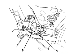
Does the starter crank the engine? YES-Go to step 11.
NO-Check the starter subharness. If the wire is OK, remove the starter (see page 4-11), then repair or replace (see page 4-13) it as necessary
11. Check the following items in the order listed until you find the problem in the circuit: NOTE: After the problem in the circuit is found and repaired, go to step 15.
- Check for an open or short in the YEL wire and connectors between the driver's under-dash fuse/ relay box and the ignition switch.
- Check for an open or short in the BLK/WHT wire and connectors between the driver's under-dash fuse/relay box and the engine wire harness TP connector.
- Check for an open or short in the ORN wire and connectors between the driver's under-dash fuse/ relay box and the clutch interlock switch (M/T model).
- Check for an open or short in the LT GRN wire, BLU/WHTwire and connectors between the driver's under-dash fuse/relay box and the transmission range switch (A/T model).
- Check for poor ground at G302 (M/T model) or G101 (A/T model).
- Check for a faulty ignition switch (see page 22-106).
- Check for a faulty clutch interlock switch (M/T model) (see page 4-9).
- Check for a faulty transmission range switch (A/T model) (see page 14-238).
- Check for a faulty starter cut relay (see page 22-93).
12. Connect the alternator, regulator, battery & starter tester (OTC3131) to the battery.
NOTE: The probe is used for starter testing.
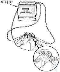
13. Do the STARTING TEST.
Does the display indicate cranking voltage is greater than or equal to 8.5 V and is the current draw less than or equal to 380 A ? YES-Go to step 14.
NO-Replace the starter (see page 4-11), or remove and disassemble it (see page 4-13), and check for these problems:
Drag in the starter armature
Short in the armature winding
Excessive drag in the engine
Open circuit in starter armature commutator segments
Excessively worn starter brushes
Open circuit in the starter brushes
Dirty or damaged helical splines or drive gear
Faulty overrunning clutch
14. Remove the starter, and inspect its drive gear and the flywheel ring gear (M/T model) or the torque converter ring gear (A/T model) for damage. Replace any damaged parts.
15. Select ECM/PCM reset (see page 11-4) in the PGM-FI INSPECTION menu to cancel ALL INJECTORS STOP with the HDS.
 Circuit Diagram
M/T model
A/T modeS
...
 Clutch Interlock Switch T e s t
M/T model
1. Disconnect the clutch interlock switch connector (A).
2. Remove the clutch interlock switch (B).
3. Check for continuity between the terminals according
to the table.
- If the ...
See also:
Using the Paddle Shifters in the D position (D-Paddle Shift Mode)
V6 models only
When you are driving in theD
position, you can shift the
transmission up or down manually
with the paddle shifters.
To shift up or down, use the +
(right) or - (left) paddl ...
Seat Heaters
EX-L and all V6 models
Both front seats are equipped with
seat heaters. Because of the sensors
for the side airbag cutoff system,
there is no heater in the passenger’s
seat-back. The igni ...
Compatible iPod®, iPhone®, and USB Flash Drives
• iPod® and iPhone® Model Compatibility
This system may not work with all software versions
of these devices.
• USB Flash Drives
• Use a recommended USB flash drive of 256 MB or higher. ...