 Honda Accord: Starter Overhaul
Disassembly/Reassembly
Armature Inspection and Test
1. Remove the starter (see page 4-11).
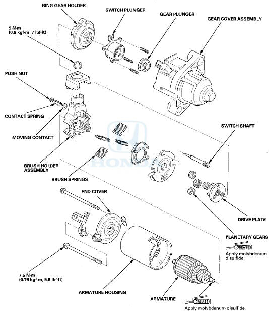
2. Disassemble the starter as shown in the Exploded View.
3. Inspect the armature for wear or damage from contact with the permanent magnet. If there is wear or damage, replace the armature.
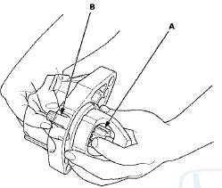
4. Check the commutator (A) surface, if the surface is dirty or burnt, resurface it with an emery cloth or a lathe to the specifications in step 5, or recondition with #500 or #600 sandpaper (B).
5. Check the commutator diameter with an electronic digital caliper or dial type caliper. If the diameter is . below the service limit, replace the armature.
Commutator Diameter
Standard (New): 28.0-28.1 mm (1.10-1.11 in)
Service Limit: 27.5 mm (1.08 in)
6. Measure the commutator (A) runout.
- If the commutator runout is within the service limit, check the commutator for carbon dust or brass chips between the segments.
- If the commutator runout is not within the service limit, replace the armature.
Commutator Runout
Standard (New): 0.02 mm (0.001 in) max.
Service Limit: 0.05 mm (0.002 in)
7. Use a digital caliper or dial caliper to check the mica depth (A). If the mica depth is below the service limit replace the armature.
Commutator Mica Depth
Standard (New): 0.40-0.50 mm (0.016-0.020 in)
Service Limit: 0.15 mm (0.006 in)
8. Use an ohmmeter to check for continuity between the segments of the commutator. If there is an open circuit between any of the segments, replace the armature.
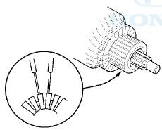
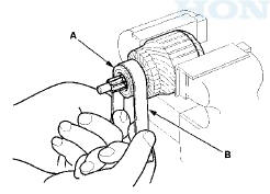
9. Place the armature (A) on an armature tester (B). Hold a hacksaw blade (C) on the armature core. If the blade is attracted to the core or vibrates while the core is turned, the armature is shorted. Replace the armature.
10. Use an ohmmeter to check for continuity between the commutator (A) and the armature coil core (B), and between the commutator and the armature shaft (C).
If there is continuity, replace the armature.
Starter Brush Inspection
11. Measure the brush length. If it is shorter than the service limit, replace the brush holder assembly.
Brush Length
Standard (New): 11.1-11.5 mm (0.44-0.45 in)
Service Limit: 4.3 mm (0.17 in)
Starter Brush Holder Test
12. Check for continuity between the {+) brushes (A) and the (-”) brushes (B). If there is continuity, replace the brush holder assembly.
P lanetary deatr inspection
13. Check the planetary gears (A) and the internal ring gear (B). Replace them if they are worn or damaged.
Overrunning Clutch Inspection
14. While holding the drive gear (A), turn the gear shaft (B) counterclockwise. Check that the drive gear comes out to the other end. If the drive gear does not move smoothly, replace the gear cover assembly.
15. While holding the drive gear, turn the gear shaft clockwise. The gear shaft should turn freely. If the gear shaft does not turn freely, replace the gear cover assembly.
16. If the drive gear is worn or damaged, replace the overrunning clutch assembly; the gear Is not available separately.
Check the condition of the flywheel ring gear (M/T model) or the torque converter ring gear (A/T model) to see If the drive gear teeth are damaged.
Starter Reassembly
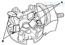
17. Install the brush Into the brush holder, and set the armature (A) In the brush holder (B).
NOTE: To seat the new brushes, slip a strip of #500 or #600 sandpaper, with the grit side up, between the commutator and each brush, and smoothly turn the armature. The contact surface of the brushes will be sanded to the same contour as the commutator.
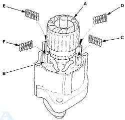
18. While squeezing a spring (C), insert it in the hole on the brush holder, and push it until it bottoms. Repeat this for the other three springs (D, E, and F).
19. Install the armature and the brush holder assembly into the housing.
NOTE: Make sure the armature stays in the holder.
 Starter Removal and
Installation
Starter Removal and
Installation
Removal
1 Do the battery removal procedure (see page 22-92).
2. Remove the intake manifold (see page 9-4).
3. Disconnect the positive starter cable (A) from the B
terminal, and the S terminal ...
 Ignition System
...
See also:
Emergency Towing
If your vehicle needs to be towed,
call a professional towing service or
organization. Never tow your vehicle
with just a rope or chain. It is very
dangerous.
There are two ways to tow your
...
Interior Lights/Interior ConvenienceItems
• Interior Light Switches
• ON
The interior lights come on regardless of
whether the doors are open or closed.
• Door activated
The interior lights come on in the following
situations: ...
Shift Cable Replacement
1. Remove the center console (see page 20-158).
2. Move the shift lever to R.
3. Remove the nut securing the shift cable end.
5. Rotate the socket holder retainer (A) counterclockwise
(B) ...