 Honda Accord: Speaker Test/Replacement
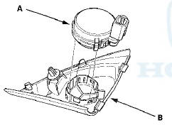
Front Door Speaker
1. Remove the door panel.
• 4-door (see page 20-17) • 2-door (see page 20-12) 2. Remove t h e bolt (A). Then lift the speaker straight up to release t h e lower clips (B).

If you pull the speaker out too far from the door, you will damage the lower clips.
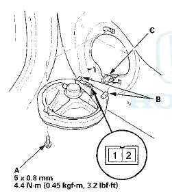
3. Disconnect the 2P connector (C), and remove the speaker.
4. Measure the resistance between the terminals No. 1 and No. 2. There should be about 4 O.
5. Ifthe resistance is not as specified, replace the door speaker.
Front Door Tweeter (With Premium Audio System)
1. Detach the clip (A) and remove the front door tweeter - cover (B). Then disconnect the connector (C).
2 . Measure the resistance between the front door
tweeter 2 P connector terminals No. 1 and No. 2 . There
should be about 3.3 .
.
3. If the resistance is not as specified, replace the front door tweeter. Remove the front door tweeter (A) from front door tweeter cover (B).

Front Door Tweeter (Without Premium Audio System)
1. Detach the clip (A) and remove the front door tweeter cover (B). Then disconnect the connector (C).
2. Remove the front door tweeter (A) from the front tweeter cover (B).
3. Check the capacitor condition. If any malfunction is found, replace the front door tweeter.
4. Measure the resistance between the front door
tweeter (A) terminal No. 2 and the outside terminal of
the capacitor. There should be about 4
.
5. If the resistance is not as specified, replace the front door tweeter.
Rear Speaker
1. Remove t h e rear shelf (see page 20-128).
2. Remove t h e mounting bolt (A), then tilt the speaker forward to release the front clips (B).

If you pull the speaker out t o o far from the rear bulkhead, you w i l l damage the lower clips.
3. Disconnect the 2P connector (C), and remove the rear speaker.
4. Measure the resistance between the terminals No. 1
and No. 2. There should be about 4.
5. If the resistance is not as specified, replace the rear speaker.
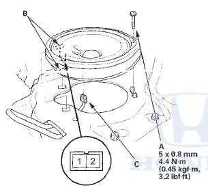
Subwoofer
1. Remove the rear shelf (see page 20-128).
2. Remove the four mounting bolts (A) from the subwoofer (B).
3. Disconnect the 2P connector (C), and remove the subwoofer.
4. Measure the resistance between the terminals No. 1 and No. 2. There should be about 2 O.
5. If the resistance is not as specified, replace the subwoofer.
 Crossover Network Control Unit
Removal/Installation
Crossover Network Control Unit
Removal/Installation
Driver's Door Speaker Crossover Network
Control Unit
1. Remove the driver's dashboard lower cover (see page
20-166).
2. Disconnect the connector (A), then remove the
driver's door speaker cross ...
 Audio Remote Switch Test
1. Remove the steering wheel (see page 17-6).
2. Remove the audio remote switch (see page 17-7).
3. Measure the resistance between the terminals No. 1
and No. 8 in each switch position accordin ...
See also:
Disc Changer Error Messages (Models with navigation system)
The chart on the right explains the
error messages you may see in the
center display while playing a disc.
If you see an error message in the
center display while playing a disc,
press the ej ...
USB Flash Memory Device Error Messages (Models with navigation system)
If you see an error message in the
center display while playing a USB
flash memory device, find the
solution in the chart to the right. If
you cannot clear the error message,
take your vehic ...
Safety Labels
These labels are in the locations
shown. They warn you of potential
hazards that could cause serious
injury or death. Read these labels
carefully.
If a label comes off or becomes hard
to ...