 Honda Accord: Rack Guide Adjustment
Special Tools Required
Locknut Wrench, 40 mm 07MAA-SL00100 or Locknut Wrench, 41 mm 07916-SA50001
1. Set the front wheels in the straight ahead position.
2. Loosen the rack guide screw locknut (A) with the locknut wrench, then remove the rack guide screw (B).
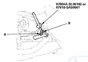
3. Remove the old sealant from the rack guide screw (A), and apply new sealant (Three Bond 1215 or Loctite 5699) to the middle of the threads (B). Loosely install the rack guide screw on the steering gearbox.
NOTE; If more than 5 minutes have passed after applying the sealant, remove the old sealant and residue, and reapply new sealant.
4. Tighten the rack guide screw (A) to 25 N-m (2.5 kgfm, 18 Ibf-ft), then loosen it.
5. Retighten the rack guide screw to 3.9 N-m (0.4 kgf-m, 2.9 Ibf-ft), then back it off to the specified angle.
Specified return angle: 15+5 В°
6. Hold the rack guide screw stationary with a wrench, and tighten the locknut by hand until it's fully seated.
7. Install the locknut wrench on the locknut (B), and hold the rack guide screw stationary with a wrench.
Tighten the locknut to the specified torque.
8. Check for unusual steering effort through the complete turning range.
9. Check the steering wheel rotation play (see page 17-4) and the power assist (see page 17-4).
 Steering Lock Replacement
1. Remove the steering column (see page 17-10).
2. Center-punch both of the two shear bolts, and drill
their heads off with a 5 mm (0.20 in) drill bit. Be careful
not to damage the steering lock ...
 Tie-rod End Ball Joint Boot Replacement
Special Tools Required
Bearing Driver Attachment, 36 07965-SA50500
1 Disconnect the tie-rod end ball joint from the knuckle
(see step 26 on page 17-41).
2. Remove the tie-rod end from the rack e ...
See also:
Cam Chain Inspection
Special Tools Required
Cam Chain inspection Gauge 07AAJ-RWCA100
1. Remove the front wheels.
2. Remove the splash shield (see step 25 on page 5-5).
3. Remove the cylinder head cover (see page 6 ...
Accessory Power Sockets
Your vehicle has two accessory
power sockets; one is at the front of
the center console and the other is in
the console compartment.
To use an accessory power socket,
the ignition switch mu ...
Windshield Washers
Check the level in the windshield
washer reservoir at least monthly
during normal use.
Check the fluid level by removing
the cap and looking at the level
gauge.
On Canadian models: The low ...