 Honda Accord: Transmission Reassembly
NOTE: Prior to reassembly, clean all the parts in solvent, dry them, and apply MTF to any contact surfaces.
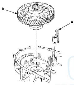
1. Install the magnet (A) and the differential assembly (B).
NOTE: Clean the magnet anytime the transmission is disassembled.
2. Install the 28 mm spring washer (A) and the 28 mm washer (B) over the ball bearing (C). Note the installation direction of the spring washer.
3. Apply vinyl tape to the mainshaft splines (D) to protect the seal. Install the mainshaft assembly (E) and the countershaft assembly (F) with the shift fork assembly (G), as an assembly.
4. Install the reverse shift fork (A).
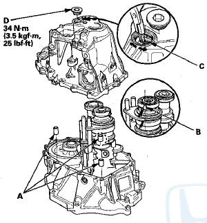
5. Install the reverse idler gear (A) and the reverse idler gear shaft (B) by aligning the mark (C) on the clutch housing with the reverse idler gear shaft hole (D).
6. Install the reverse lock cam (A).
7. Install the baffle plate (A).
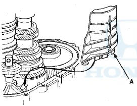
8. Select the proper size 72 mm shim (A) according to the measurements made during the Mainshaft Thrust Clearance Adjustment (see page 13-56). Install the oil gutter plate (B), oil guide plate M, and the 72 mm shim into the transmission housing (C).
9. Clean any dirt or oil from the transmission housing sealing surface.
10. Apply liquid gasket, P/N 08717-0004,08718-0001, 08718-0003, or 08718-0009 evenly to the clutch housing mating surface of the transmission housing.
Install the component within 5 minutes of applying the liquid gasket.
NOTE: - If apply liquid gasket P/N 08718-0012, the component must be installed within 4 minutes.
- If too much time has passed after applying the liquid gasket, remove the old liquid gasket and residue, then reapply new liquid gasket.
11. Install the three 14 x 20 mm dowel pins (A).
12. Set the tapered cone ring (B) as shown. Place the
transmission housing on the clutch housing, making
sure to line up the shafts.
13. While expanding the 72 mm snap ring (C) on the countershaft ball bearing using snap ring pliers, push the transmission housing down to start the countershaft ball bearing through the snap ring.
Release the pliers, and push down the housing until it bottoms and the snap ring snaps in place in the countershaft ball bearing snap ring groove.
NOTE: Install the 32 mm sealing cap (D) after setting in the 72 mm snap ring.
14. Make sure the 72 mm snap ring (A) is securely seated in the groove of the countershaft bearing.
16. Install the 8 mm flange bolts finger-tight with
transmission hanger A and transmission hanger B.
17. Tighten the 8 mm flange bolts in a crisscross pattern in several steps.
Specified Torque: 8 x 1.25 mm
27 Nm (2.8 kgf-m, 20 Ibfft)
18. Clean any dirt or oil from the change lever assembly sealing surface.
19. Apply liquid gasket, P/N 08717-0004,08718-0001, 08718-0003, or 08718-0009 evenly to the transmission housing mating surface of the change lever assembly.
Install the component within 5 minutes of applying the liquid gasket NOTE; - If apply liquid gasket P/N 08718-0012, the component must be installed within 4 minutes.
- If too much time has passed after applying the liquid gasket, remove the old liquid gasket and residue, then reapply new liquid gasket.
20. Install the 8 x 1 4 mm dowel pins (A) and the change lever assembly (B).
21. Apply liquid gasket (P/N 08717-0004,08718-0001, 08718-0012,08718-0003, or 08718-0009) to the threads of the interlock bolt (C), and install it on the transmission housing.
22. Install the filler plug (A) with a new washer finger-tight, and install the drain plug (B) and the 10 mm flange bolt (C) with new sealing washers (D).
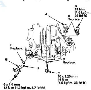
23. Apply MTF to a new O-ring (E), then install the O-ring, the plain washer (F), and the output shaft (countershaft) speed sensor (G).
24. Install the steel balls (A), the springs (B), the detent bolts (D) with new 12 mm sealing washers (E).
25. Install the 20 mm bolt (F) with a new 20 mm sealing washer (G), and transmission hanger C.
26. Apply liquid gasket (P/N 08717-0004,08718-0001, 08718-0012, 08718-0003, or 08718-0009) to the threads of the back-up light switch (H), and install it in the transmission housing.
 Mainshaft Thrust Clearance Adjustment
Special Tools Required
- Mainshaft Holder 07GAJ-PG20110
- Mainshaft Base 07GAJ-PG20130
1. Remove the 72 mm shim (A) and oil guide plate M
from the transmission housing (B).
2. Thoroughly clea ...
 Gearshift Mechanism Replacement
NOTE: Make sure not to get any silicone grease on the terminal part of the
connectors and switches, especially if you
have silicone grease on your hands or gloves.
...
See also:
DTC Troubleshooting Index
NOTE: Before you troubleshoot record all freeze data and any on-board
snapshot with the HDS, and review General
Troubleshooting Information (see page 14-4).
NOTE:
*1: The DTC in parentheses is ...
Symptom Troubleshooting Index
Find the symptom in the chart below, and do the related procedures in the
order listed until you find the cause.
...
A/C Compressor Replacement
NOTE: Do not install the A/C compressor into a system
unless you are completely sure that the system is free of
contamination. Installing the A/C compressor into a
contaminated system can result in ...