 Honda Accord: System Description
General Description
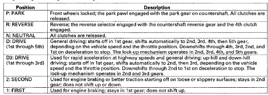
The automatic transmission is a transverse-mounted three-shaft design, implemeting an electronically controlled hydraulic circuit that provides five forward speeds and one in reverse. Engine power is transmitted through the torque converter, a combination of shafts which hold gears and clutches and a differential that transmits power to the driving wheels.
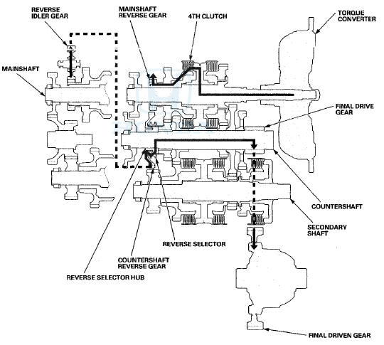
Shaft, Gears and Clutches
Three parallel shafts hold gears and clutches. The gears on the input shaft (mainshaft) and secondary shaft are in constant mesh with those on the output shaft (countershaft). When specific gears are engaged by the clutches, power is transmitted through the mainshaft, to the secondary shaft, and/or the countershaft, then to the final drive gear of the differential to provide drive.
Shift Control Mechanism
To shift gears, the PCM controls shift solenoid valves A, B, C, D and E, and automatic transmission (A/T) clutch pressure control solenoid valves Ar B, and C. The shift solenoid valves change the positions of the shift valves in the valve body which open and close ports to send hydraulic pressure to the appropriate clutch.
Electronic Control
Shifting' and lock-up is achieved by a system of solenoid valves driven by the PCM to control ATF flow through various valves in the valve bodies to select the appropriate gears for ail driving conditions.
Hydaulic Control
The valve bodies include the main valve body, the regulator valve body, the secondary valve body. They are mounted to the torque converter housing. Fluid from the regulator valve passes through the manual valve to the various control valves. All the clutches receive fluid from the internal hydraulic circuit.
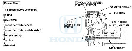
Torque Converter
The torque converter is a fluid coupling, which allows the engine to spin independently of the transmission yet connects them together as needed. It is an assembly that consists of an impeller (pump), turbine, stator and lock-up clutch, which uses automatic transmission fluid (ATF) to transmit engine power to the input shaft (mainshaft), and acts as a flywheel to help the engine run smoothly. During certain conditions the lock-up clutch is engaged by the PCM to mechanically connect the engine's crankshaft with the input shaft (mainshaft) which improves fuel economy. Around the outside of the torque converter housing is a ring gear which meshes with the starter ring gear, when the engine is being started.
Lock-up Mechanism
The lock-up mechanism causes the input shaft (mainshaft) to rotate at the same speed as the engine crankshaft.
Pressurized ATF is drained from between the torque converter cover and the torque converter clutch piston through a fluid passage, causing the torque converter clutch piston to be held against the torque converter housing. Together with the hydraulic control, the PCM optimizes the timing and degree of lock-up. The lock-up mechanism operates in D (2nd, 3rd, 4th, and 5th gears) and D3 (1st, 2nd, and 3rd gears).
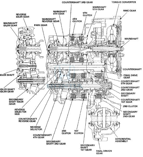
Gear Selection
The shift lever has seven positions; P: PARK, R: REVERSE, N: NEUTRAL, D: 1st through 5th gear ranges, D3:1st through 3rd gear ranges, 2: 2nd gear, and 1:1 st gear.
Starting is possible only in P and N because of a neutral-safety switch.
Automatic Transmission (A/T) Gear Position Indicator
The A/T gear position indicator in the gauge control module shows which shift lever position has been selected.
Clutches and Gears
The five-speed automatic transmission uses hydraulically-actuated clutches to engage or disengage the transmission gears. When hydraulic pressure is introduced into the clutch drum, the clutch piston moves. This presses the friction discs and the steel plates together, locking them so they do not slip. Power is then transmitted through the engaged clutch pack to its hub-mounted gear. Likewise/when the hydraulic pressure is bled from the clutch pack, the piston releases the friction discs and the steel plates, and they are free to slide past each other. This allows the gear to spin independently on its shaft, transmitting no power.
1st Clutch
The 1st clutch engages/disengages 1st gear, and is located at the middle of the secondary shaft. The 1st clutch is joined back-to-back to the 3rd clutch. The 1st clutch is supplied hydraulic pressure by its ATF feed pipe within the secondary shaft.
2nd Clutch
The 2nd clutch engages/disengages 2nd gear, and is located at the end of the secondary shaft, opposite the end cover.
The 2nd clutch is supplied hydraulic pressure by a circuit connected to the internal hydraulic circuit
Sid Clutch
The 3rd clutch engages/disengages 3rd gear, and is located at the middle of the secondary shaft. The 3rd clutch is joined back-to-back to the 1st clutch. The 3rd clutch is supplied hydraulic pressure by its ATF feed pipe within the secondary shaft.
4th Clutch
The 4th clutch engages/disengages 4th gear, as well as reverse gear, and is located at the middle of the mainshaft. The 4th clutch is joined back-to-back to the 5th clutch. The 4th clutch is supplied hydraulic pressure by its ATF feed pipe within the mainshaft.
5th Clutch
The 5th clutch engages/disengages 5th gear, and is located at the middle of the mainshaft. The 5th clutch is joined back-to-back to the 4th clutch. The 5th clutch is supplied hydraulic pressure by its ATF feed pipe within the mainshaft
Gear operation
Gears on the mainshaft; •4th gear engages/disengages with the mainshaft by the 4th clutch.
-5th gear engages/disengages with the mainshaft by the 5th clutch.
•Reverse gear engages/disengages with the mainshaft by the 4th clutch, -Idler gear is splined with the mainshaft, and rotates with the mainshaft.
Gears on the countershaft:
-Final drive gear is integral with the countershaft.
-1 st, 2nd, 3rd, 5th, and park gears are splined with the countershaft, and rotate with the countershaft.
-4th gear and reverse gear rotate freely from the countershaft. The reverse selector engages 4th gear and reverse gear with the reverse selector hub. The reverse selector hub is splined to the countershaft so that 4th gear and the reverse gear engage with the countershaft.
Gears on the secondary shaft:
- 1st gear engages/disengages with the secondary shaft by the 1 st clutch.
- 2nd gear engajes/disengages with the secondary shaft by the 2nd clutch.
- 3rd gear engages/disengages with the secondary shaft by the 3rd clutch.
- Idler gear is splined with the secondary shaft, and rotates with the secondary shaft.
The idler gear on the idler shaft transmits power between the mainshaft and the secondary shaft.
The reverse idler gear transmits power from the mainshaft reverse gear to the countershaft reverse gear, and changes rotational direction of the countershaft to reverse.
Transmission Cutaway View
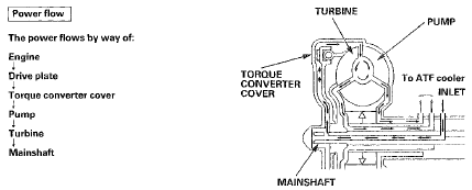
Power Flow
P Position
Hydraulic pressure is not applied to the clutches. Power is not transmitted to the countershaft. The countershaft is locked by the park pawl interlocking the park gear.
N Position
Engine power transmitted from the torque converter drives the mainshaft idler gear, the idler shaft idler gear, and the secondary shaft idler gear, but hydraulic pressure is not applied to the clutches. Power is not transmitted to the countershaft.
In this position, the position of the reverse selector differs according to whether the shift lever shifted from D or R: -When shifted from D, the reverse selector engages with the countershaft 4th gear and the reverse selector hub, and 4th gear engages with the countershaft.
-When shifted from R, the reverse selector engages with the countershaft reverse gear and the reverse selector hub, and the reverse gear engages with the countershaft.
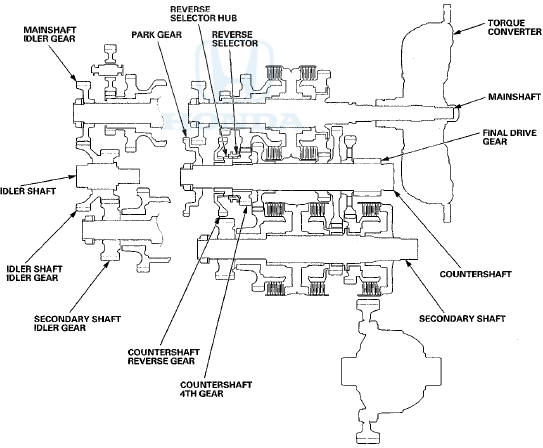
In 1st Gear
-Hydraulic pressure is applied to the 1st clutch, then the 1st clutch engages the secondary shaft 1st gear with the secondary shaft.
-The mainshaft idler gear drives the secondary shaft via the idler shaft idler gear and the secondary shaft idler gear.
-The secondary shaft 1st gear drives the countershaft 1st gear and the countershaft.
-Power is transmitted to the final drive gear, which in turn drives the final driven gear.
Power Flow (cont'd)
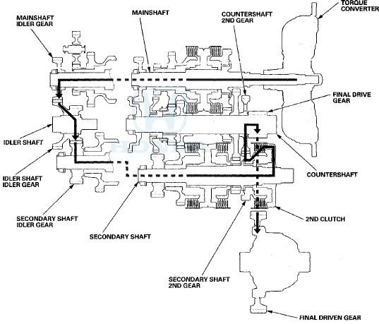
In 2nd Gear
-Hydraulic pressure is applied to the 2nd clutch, then the 2nd clutch engages the secondary shaft 2nd gear with the secondary shaft.
-The mainshaft idler gear drives the secondary shaft via the idler shaft idler gear and the secondary shaft idler gear.
-The secondary shaft 2nd gear drives the countershaft 2nd gear and the countershaft.
-Power is transmitted to the final drive gear, which in turn drives the final driven gear.
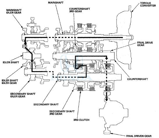
In 3rd Gear
-Hydraulic pressure is applied to the 3rd clutch, then the 3rd clutch engages the secondary shaft 3rd gear with the secondary shaft.
-The mainshaft idler gear drives the secondary shaft via the idler shaft idler gear and the secondary shaft idler gear.
-The secondary shaft 3rd gear drives the countershaft 3rd gear and the countershaft.
-Power is transmitted to the final drive gear, which in turn drives the final driven gear.
Power Flow
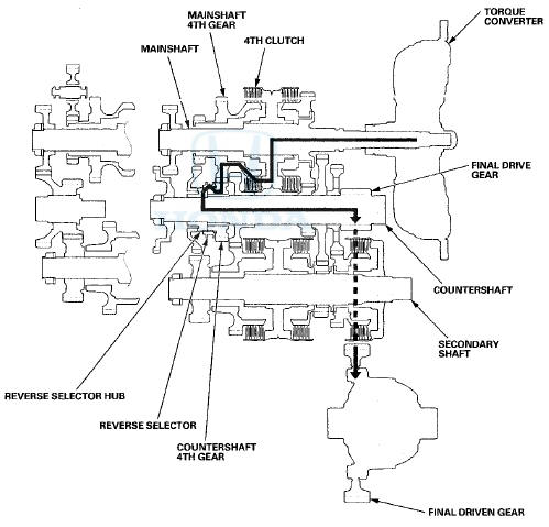
In 4th Gear
-Hydraulic pressure is applied to the servo valve to engage the reverse selector with the countershaft 4th gear and the reverse selector hub while the shift lever is in forward range (D, D3,2, and 1).
-Hydraulic pressure is also applied to the 4th clutch, then the 4th clutch engages the mainshaft 4th gear with the mainshaft.
-The mainshaft 4th gear drives the countershaft 4th gear and the countershaft.
-Power is transmitted to the final drive gear, which in turn drives the final driven gear.
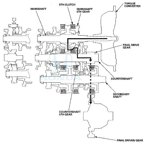
In 5th Gear
-Hydraulic pressure is applied to the 5th clutch, then the 5th clutch engages the mainshaft 5th gear with the mainshaft.
-The mainshaft 5th gear drives the countershaft 5th gear and the countershaft.
-Power is transmitted to the final drive gear, which in turn drives the final driven gear.
Power Flow (cont'd)
R Position
-Hydraulic pressure is applied to the servo valve to engage the reverse selector with the countershaft reverse gear and the reverse selector hub while the shift lever is in R.
-Hydraulic pressure is also applied to the 4th clutch, then the 4th clutch engages the mainshaft reverse gear with the mainshaft.
-The mainshaft reverse gear drives the countershaft reverse gear via the reverse idler gear.
-The rotation direction of the countershaft reverse gear is changed by the reverse idler gear. .
-The countershaft reverse gear drives the countershaft via the reverse selector, which drives the reverse selector hub.
-Power is transmitted to the final drive gear, which in turn drives the final driven gear.
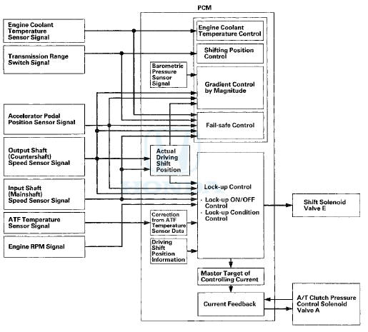
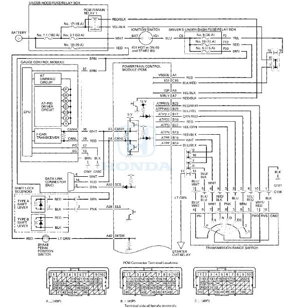
Electronic Control System
Electronic Control
The electronic control system consists of the powertrain control module (PCM), sensors, and solenoid valves.
Functional Diagram
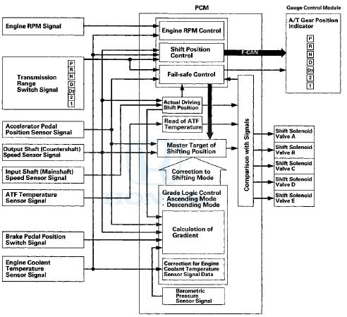
The PCM receives input signals from sensors, switches, and other control units, processes data, and outputs signals for the engine control system and the A/T control system. The A/T control system includes shift control, grade logic control, clutch pressure control, and lock-up control. The PCM switches the shift solenoid valves and the A/T clutch pressure control solenoid valves to control shifting transmission gears and lock-up torque converter clutch.
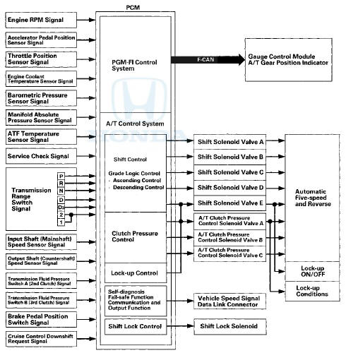
Shift Control
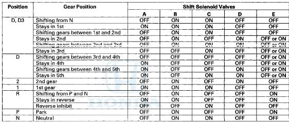
The PCM instantly determines which gear should be selected by various signals sent from sensors and switches, and it actuates shift solenoid valves A, B, C, D, and E to control gear selection.
The PCM turns shift solenoid valves A, B, C, D, and E ON and OFF to control gear selection. AH shift solenoid valves are normally closed (ON-OPEN/OFF-CLOSED). The shift solenoid valve port opens to allow ATF to pass through when the PCM turns it ON, and the port closes, blocking fluid flow when turned ON. The combination of driving signals to shift solenoid valves A, B, C, D, and E for each year are in the following table.
Shift Control-Grade Logic
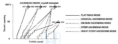
A grade logic control system is used to control shifting in D and D3. The PCM compares actual driving conditions with programmed driving conditions, based on the input from the accelerator pedal position sensor, the engine coolant temperature sensor, the barometric pressure sensor, the brake pedal position switch signal, and the shift lever position signal, to improve shifting control while the vehicle is ascending or descending a slope.
Grade Logic .Control: Ascending Control
When the PCM determines that the vehicle is climbing a hill in D and D3, the system extends the engagement area of 2nd, 3rd, and 4th gears to prevent the transmission from frequently shifting between 2nd and 3rd gears, between 3rd and 4th gears, and between 4th and 5th gears, so the vehicle can run smooth and have more power when needed.
Shift programs stored in the PCM between 2nd and 3rd gears, between 3rd and 4th gears, and between 4th and 5th gears, enable the PCM to automatically select the most suitable gear based on the steepness of the grade.
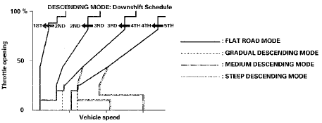
Grade Logic Control: Descending Control
When the PCM determines that the vehicle is going down a hill in D and D3, the upshift speed from 4th to 5th gear, from 3rd to 4th gear, and from 2nd to 3rd gear (when the throttle is closed) becomes higher than the set speed for flat road driving to extend the 4th gear, 3rd gear, and 2nd gear driving area. This, in combination with engine braking from the deceleration lock-up, achieves smooth driving when the vehicle is descending. There are three descending modes stored in the PCM with different 4th gear, 3rd gear, and 2nd gear driving areas based on the steepness of the grade.
When the vehicle is in 5th gear or 4th gear, and the vehicle is decelerating while applying the brakes on a steep hill, the transmission will downshift to lower gear. When you accelerate, the transmission will then return to a higher gear.
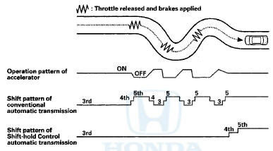
Shift-Hold Control
When driving on winding roads, the throttle is suddenly released and the brakes are applied, as is the case when decelerating at the entrance of a curve, shift-hold control keeps the transmission in its current (lower) ratio as it negotiates the corner and accelerates out.
When the vehicle is driven aggressively on a winding road, the PCM extends the engagement time of 3rd gear and 4th gear to prevent the transmission from frequently shifting between 3rd, 4th, and 5th gears.
The PCM monitors the average change in the vehicle speed and throttle over time. When these values exceed those for normal driving conditions, the upshift from 3rd to 4th gear and 4th to 5th gear is delayed. This gives more control over power, and the engine braking. The transmission resumes the normal upshift pattern after the PCM determines that normal driving has resumed.
Clutch Pressure Control
The PCM actuates A/T clutch pressure control solenoid valves A, B, and C to control the clutch pressure. When shifting between lower and higher gears, the clutch pressure regulated by A/T clutch pressure control solenoid valves A, B, and C engages and disengages the clutch smoothly.
The PCM receives input signals from the various sensors and switches, processes data, and outputs current to A/T clutch pressure control solenoid valves A, B, and C.
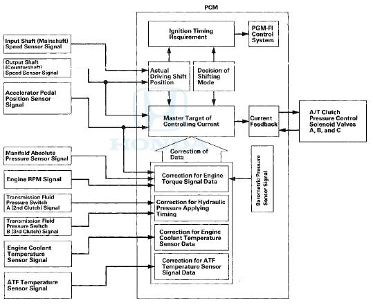
Lock-up Control
Shift solenoid valve E controls the hydraulic pressure to switch the lock-up shift valve ON and OFF, The PCM actuates shift solenoid valve E and A/T clutch pressure control solenoid valve A, lock-up start. A/T clutch pressure control solenoid valve A applies and regulates hydraulic pressure to the iock-up control valve to control the volume of the lock-up.
The lock-up mechanism operates in D (2nd, 3rd, 4th, and 5th gears), and in D3 (2nd and 3rd gears).
Self-diagnosis
If the PCM detects the failure of a signal from a sensor, a switch, a solenoid valve, or from another control unit, it stores a Pending or Confirmed DTC. Depending on the failure, a Confirmed DTC is stored in either the first or the second drive cycle. When a DTC is stored, the PCM blinks the D indicator and/or turns on the malfunction indicator lamp (MIL) by a signal sent to the gauge control module via F-CAN.
-One Drive Cycle Detection Method:
When an abnormality occurs in the signal from a sensor, a switch, a solenoid valve, or from another control unit, the PCM stores a Confirmed DTC for the failure and blinks the D indicator and/or turns on the MIL immediately.
-Two Drive Cycle Detection Method:
When an abnormality occurs in the signal from a sensor, a switch, a solenoid valve, or from another control unit in the first drive cycle, the PCM stores a Pending DTC. The D indicator and the MIL do not turns on at this time. If the failure continues in the second drive cycle, the PCM stores a Confirmed DTC and blinks the D indicator and/or turns on the MIL.
Fail-safe Function
When an abnormality occurs in the signal from a sensor, a switch, a solenoid valve, or from another control unit, the PCM ignores it and substitutes a pre-programmed value for that signal to allow the automatic transmission to continue operating. This causes a DTC to be stored and the D indicator to blink and/or the MIL to come on. The transmission may not shift normally during fail-safe operation. Do not run the test driving diagnosis when the MIL is ON, or the D indicator is blinking.
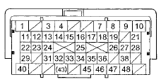
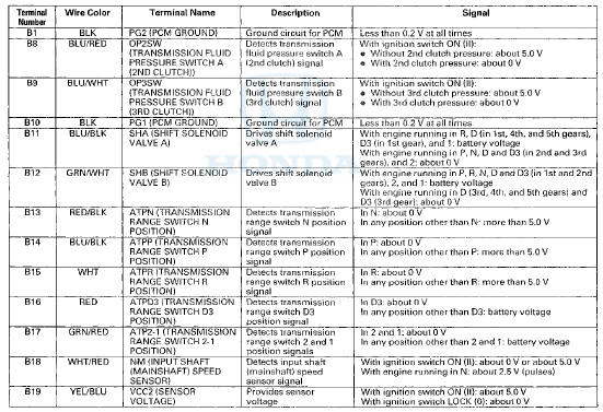
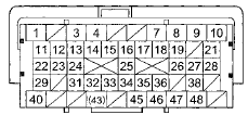
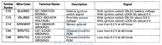
PCMA/T Control S f stem Electrical Connections
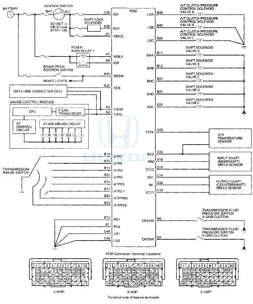
PCMA/T Control S f stem Inputs and Outputs at PCM Connector A
 (49P)
(49P)
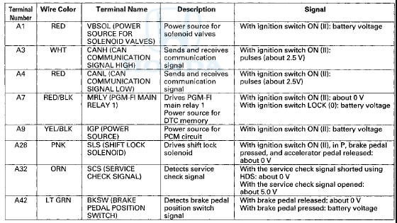
PCMA/T Control S f stem Inputs and Outputs at PCH Connector B A |49P)
Terminal side of female terminals
PCMA/I Control System Inputs and Outputs at PCSVI Connector B
 (49P)
(49P)
Terminal side of female terminals
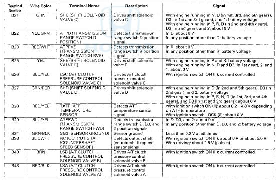
PCMA/T Control S f stem inputs and Outputs at PCM Connector C O (49P)
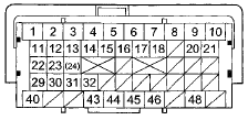
Terminal side of female terminals
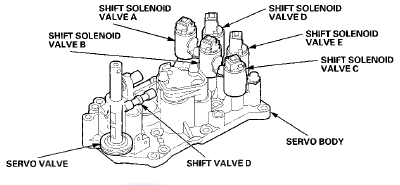
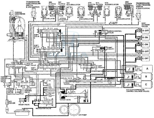
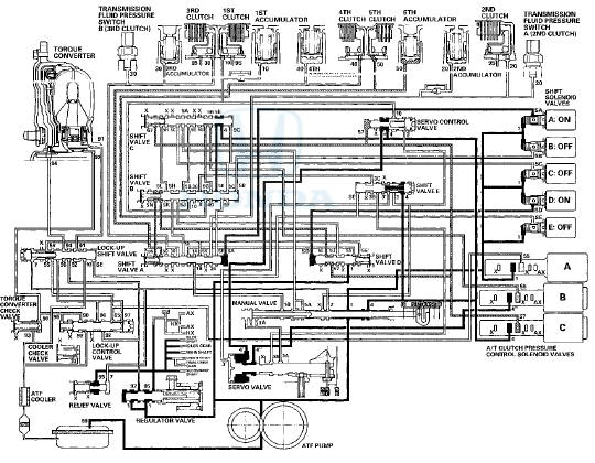
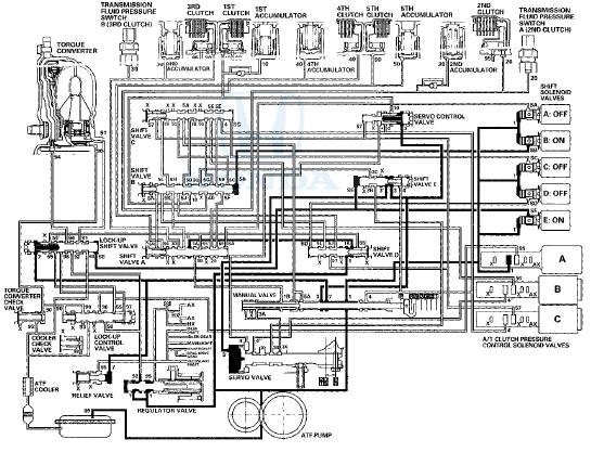
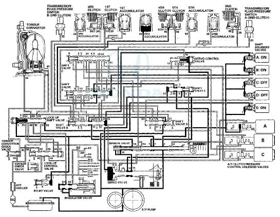
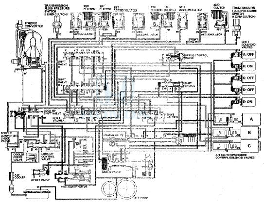
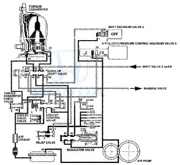
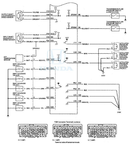
Hydraulic Controls
Valve Bodies
The valve body includes the main valve body, the regulator valve body, and the servo body. The ATF pump is driven by splines on the end of the torque converter which is attached to the engine. Fluid flows through the regulator valve to maintain specified pressure through the main valve body to the manual valve, directing pressure to the shift valves and to each of the clutches via the solenoid valves. Shift solenoid valves A, B, C, D, and E are bolted on the servo body. A/T clutch pressure control solenoid valves A, B, and C are mounted on the outside of the transmission housing.
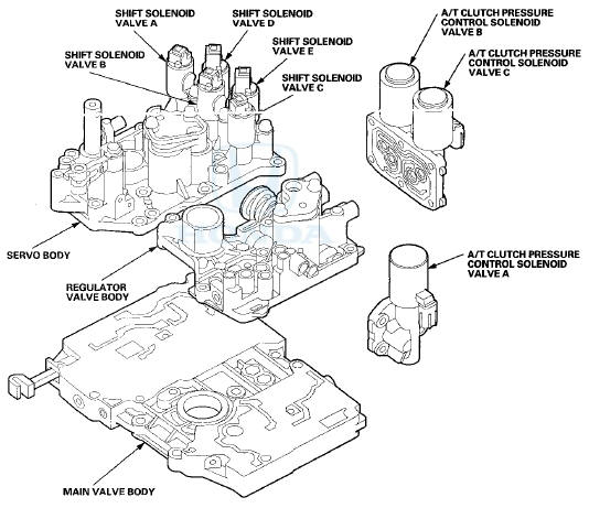
Main Valve Body
The main valve body contains the manual valve, shift valves A, B, C, and E, the relief valve, the lock-up control valve, the cooler check valve, the servo control valve, and the ATF pump gears. The primary function of the main valve body is to switch fluid pressure on and off and to control hydraulic pressure going to the hydraulic control system.
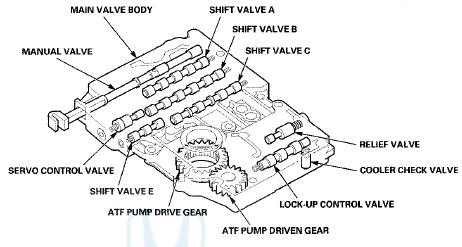
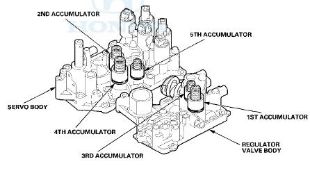
Regulator Valve Body
The regulator valve body contains the regulator valve, the torque converter check valve, the lock-up shift valve, and the 1st and 3rd accumulators.
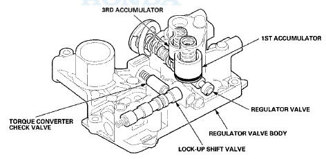
Regulator Valve
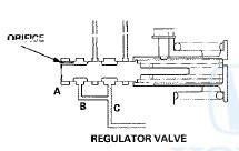
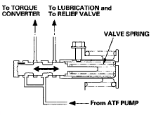
The regulator valve maintains constant hydraulic pressure from the ATF pump to the hydraulic control system, while also providing fluid to the lubrication system and the torque converter. The fluid from the ATF pump flows through B and C. Fluid entering from B flows through the valve orifice to the A cavity. This pressure in the A cavity pushes the regulator valve toward the valve spring side, and this movement of the regulator valve uncovers the fluid port to the torque converter and the relief valve. The fluid flows out to the torque converter and the relief valve, and the regulator valve returns under spring force. According to the level of the hydraulic pressure through B, the position of the regulator valve changes, and the amount of fluid from C through torque converter also changes. This operation is continuous, maintaining the line pressure.
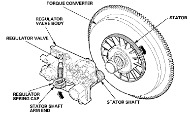
Increases in hydraulic pressure according to torque are regulated by the regulator valve using stator torque reaction.
The stator shaft is splined with the stator in the torque converter, and the stator shaft arm end contacts the regulator spring cap. When the vehicle is accelerating or climbing (torque converter range), stator torque reaction acts on the stator shaft, and the stator shaft arm pushes the regulator spring cap in the direction of the arrow in proportion to the reaction. The stator reaction spring compresses, and the regulator valve moves to increase the line pressure which is regulated by the regulator valve. The line pressure reaches its maximum when the stator torque reaction reaches its maximum.
Servo Body
The servo body contains the servo valve, shift valve D, the accumulators for 2nd, 4th, and 5th, and shift solenoid valves A, B, C, D, and E.
Accumulator
The accumulators are located in the regulator valve body and the servo body. The regulator valve body contains the 1st and 3rd accumulators, and the servo body contains the 2nd, 4th, and 5th accumulators.
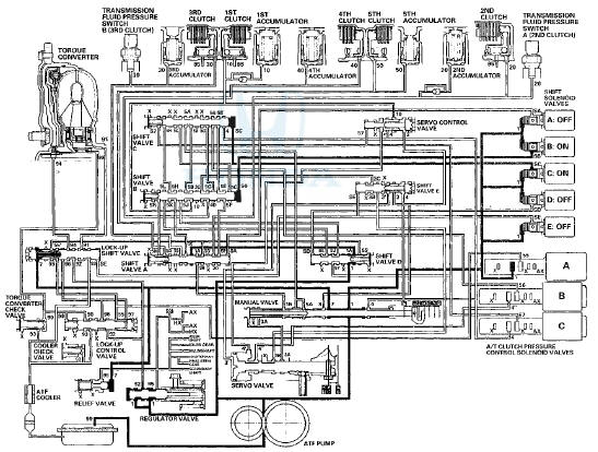
Hydraulic Flow
Distribution of Hydraulic Pressure
As the engine turns, the ATF pump starts to operate. Automatic transmission fluid (ATF) is drawn through the ATF strainer (filter) and discharged into the hydraulic circuit. Then, ATF flowing from the ATF pump becomes line pressure that is regulated by the regulator valve. Torque converter pressure from the regulator valve enters the torque converter through the lock-up shift valve, and it is discharged from the torque converter. The torque converter check valve prevents torque converter pressure from rising.
The PCM turns the shift solenoid valves ON and OFF. The shift solenoid valve intercepts line pressure from the ATF pump via the manual valve when the shift solenoid valve is OFF. When the shift solenoid valve is turned ON by the PCM, line pressure changes to shift solenoid valve pressure at the shift solenoid valve, then the shift solenoid valve pressure flows to the shift valve. Applying shift solenoid pressure to the shift valves moves the position of the shift valve, and switches the port of the hydraulic circuit. The PCM also controls A/T clutch pressure control solenoid valves A, B, and C.
The A/T clutch pressure control solenoid valves regulate hydraulic pressure, and applies the pressure to the clutches to engage smoothly. The clutches receive optimum clutch pressure which is regulated by the A/T clutch pressure control solenoid valves for comfortable driving and shifting under all conditions.
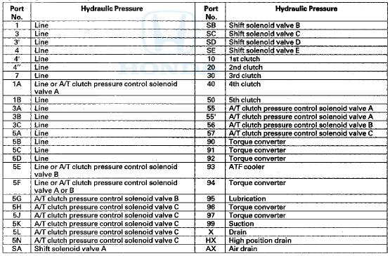
Hydraulic pressure at the port for use in the hydraulic circuit
N Position
The PCM controls the shift solenoid valves. The conditions of the shift solenoid valves and the positions of the shift .valves are as follows:
-Shift solenoid valve A: OFF, and shift valve A remains on the right side
-Shift solenoid valve B: ON, and shift valve B moves to the left side
-Shift solenoid valve C: ON, and shift valve C moves to the left side
-Shift solenoid valve D: OFF, and shift valve D remains on the left side
-Shift solenoid valve E; OFF, and shift valve E remains on the left side
Line pressure (1) flows to the shift solenoid valves and A/T clutch pressure control solenoid valve A. Under this condition, hydraulic pressure is not applied to the clutches.
NOTE: When used, "left" or "right" indicates direction on the hydraulic circuit.
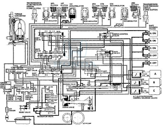
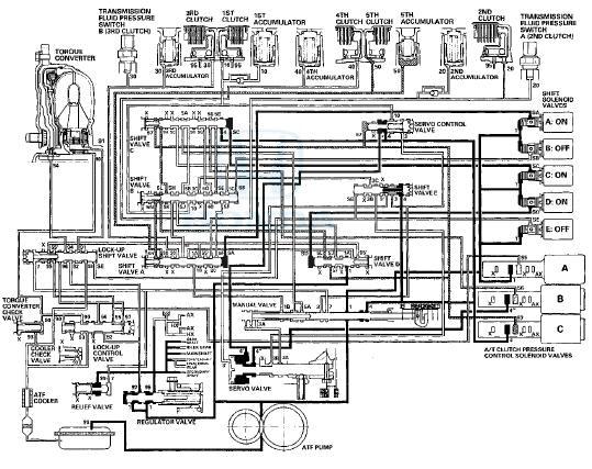
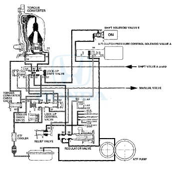
D Position; 1st gear shifting from N position
The shift solenoid valves remain the same as in N when shifting to D from N. The manual valve is moved to D, and uncovers the line pressure port (4) leading to A/T clutch pressure control solenoid valve C. Hydraulic pressure to the 1st clutch from A/T clutch pressure control solenoid valve A is created as shift solenoid valve A is OFF, B and C remain ON.
A/T clutch pressure control solenoid valve A pressure (55) changes to 1st clutch pressure (10) at shift valve B, and flows to the 1st clutch. The 1st clutch is engaged gently when shifting to D from N.
NOTE: When used, "left" or "right" indicates direction on the hydraulic circuit.
D Position: Driving in 1st gear
The PCM turns shift solenoid valve A ON, B and C remain ON, and D and E remain OFF. Shift solenoid valve A pressure (SA) is applied to the right side of shift vajve A. Shift valve A is moved to the left side to uncover the line pressure port leading to the 1st clutch, and to cover the A/T clutch pressure control solenoid valve pressure port.
Fluid flows to the 1 st clutch by way of:
Line pressure (1)  Shift valve
D—Line pressure (1A)  Shift valve
A—Line pressure (1B) Manual
valve—Line
pressure (5A)  Shift valve C—Line
pressure (5B)  Shift valve B —1st
clutch pressure (10)  1st clutch
1st clutch pressure (10) is applied to the 1st clutch, and the 1st clutch is
engaged securely.
NOTE: When used, "left" or "right" indicates direction on the hydraulic circuit.
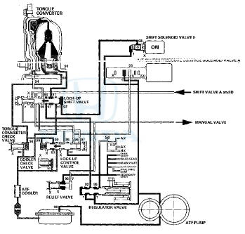
D Position; Shifting between 1st gear and 2nd gear
As the speed of the vehicle reaches the programmed value, the PCM turns shift solenoid valve A OFF, B and C remain ON, and D and E remain OFF. Shift solenoid valve A pressure (SA) in the right side of shift valve A is released. Shift valve A moves to the right side uncovering the A/T clutch pressure control solenoid valve pressure port leading to the 1st and 2nd clutches. The PCM controls the A/T clutch pressure control solenoid valves to regulate hydraulic pressure. A/T clutch pressure control solenoid valve A pressure (55) changes to 1 st clutch pressure (10) at shift valve B, and A/T clutch pressure control solenoid valve B pressure (66) changes to 2nd clutch pressure (20) at shift valve A. The 1st and 2nd clutches are engaged gently.
NOTE: When used, "left" or "right" indicates direction on the hydraulic circuit.
D Position; Driving in 2nd gear
The PCM turns shift solenoid valves C OFF, D ON, A and E remain OFF, and B remains ON. Shift solenoid valve C pressure (SC) in the right side of shift valve C is released. Shift valve C moves to the right side to switch the ports. This movement covers the ports to block the A/T clutch pressure control solenoid valve pressure at shift valves C and A, and uncover the line pressure port leading to the 2nd clutch.
Fluid flows to 2nd clutch by way of:
Line pressure (1) Manual
valve—Line pressure (4) Shift
valve C—Line pressure (5E) Shift
valve B —Line pressure
(5F)Shift valve A—2nd clutch
pressure (20)2nd clutch
2nd clutch pressure (20) is applied to the 2nd clutch, and the 2nd clutch is
engaged securely.
NOTE: When used, "left" or "right" indicates direction on the hydraulic circuit.
D Position: Shifting between 2nd gear and 3rd gear
As the speed of the vehicle reaches the programmed value, the PCM turns shift solenoid valve C ON, A and E remain OFF, and B and D remain ON. Shift solenoid valve C pressure (SC) is applied to the right side of shift valve C. Shift valve C moves to the left side uncovering the A/T clutch pressure control solenoid valve pressure ports leading to the 2nd and 3rd clutches. The PCM controls the A/T clutch pressure control solenoid valves to regulate hydraulic pressure. A/T clutch pressure control solenoid valve B pressure (56) changes to 2nd clutch pressure (20) at shift valve A, and A/T clutch pressure control solenoid valve C pressure (57) changes to 3rd clutch pressure (30) at shift valve A. The 2nd and 3rd clutches are engaged gently.
NOTE: When used, "left" or "right" indicates direction on the hydraulic circuit.
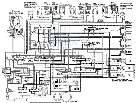
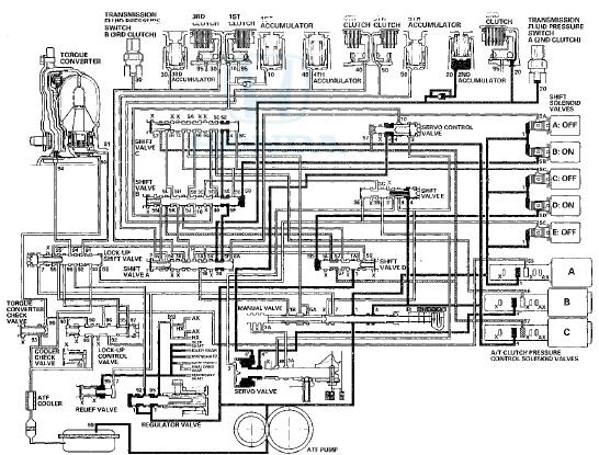
D Position: Driving in 3rd gear
The PCM turns shift solenoid valves B and D OFF, A and E remain OFF, and C remains ON. Shift solenoid valve B pressure (SB) in the right side of shift valve B is released, and shift valve B moves to the right side. Shift solenoid valve D pressure (SD) in the left side of shift valve D is released, and shift valve D is moved to the left side. This valve movement causes A/T clutch pressure control solenoid valve C pressure to be directed to the port leading to the 3rd clutch.
A/T clutch pressure control solenoid valve C pressure (57) changes to (5J) at shift solenoid valve D and to (5K) at shift valve B, and becomes 3rd clutch pressure (30) at shift valve A. 3rd clutch pressure (30) is applied to the 3rd clutch, and the 3rd clutch is engaged securely.
NOTE: When used, "left" or "right" indicates direction on the hydraulic circuit.
D Position; Shifting between 3rd gear and 4th gear
As the speed of the vehicle reaches the programmed value, the PCM turns shift solenoid valve C OFF, and A, B, D, and E remain OFF. Shift solenoid valve C pressure (SC) in the right side of shift valve C is released. Shift valve C is moved to the right side uncovering the A/T clutch pressure control solenoid valve B and C pressure ports leading to the 3rd and 4th clutches. The PCM controls the A/T clutch pressure control solenoid valves to regulate hydraulic pressure. A/T clutch pressure control solenoid valve C pressure (57) changes to 3rd clutch pressure (30) at shift valve A, and A/T clutch pressure control solenoid valve B pressure (56) changes to 4th clutch pressure (40) at shift valve B. The 3rd and 4th clutches are engaged gently.
NOTE: When used, "left" or "right" indicates direction on the hydraulic circuit.
D Position: Driving in 4th gear
The PCM turns shift solenoid valve A ON, and B, C, 0, and E remsin OFF. Shift solenoid tfalve A pressure (SA) is applied to the right side of shift valve A. Shift valve A is moved to the left side to cover the PJT clutch pressure control solenoid valve A and C pressure ports leading to the 2nd and 3rd clutches.
A/T clutch pressure control solenoid valve B pressure (56) changes to ibd) at shift valve C. and becomes 4th clutch pressure (40) at shift valve B. 4th clutch pressure (40) is held h'.gh 'by A T ciuich pressure control solenoid valve B, and the 4th clutch is engaged securely.
NOTE: When used, "left" or "right" indicates direction on tr.s hydraulic circuit
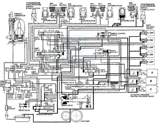
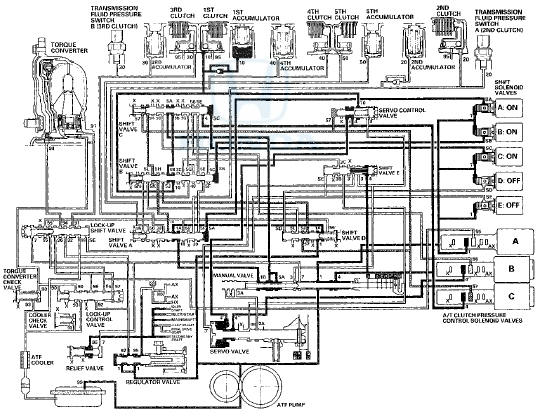
D Position: Shifting between 4th gear and 5th gear
As the speed of the vehicle reaches the programmed value, the PCM turns shift solenoid valve D ON, A remains ON, and B, C, and E remain OFF. Shift solenoid valve D pressure (SD) is applied to the left side of shift valve D. Shift valve D is moved to the right side uncovering the A/T clutch pressure control solenoid valve C pressure port leading to the 5th clutch. A/T clutch pressure control solenoid valve B pressure (56) changes to 4th clutch pressure (40) at shift valve B. A/T clutch pressure control solenoid valve C pressure (57) changes to (5L) at shift valve D and to (5N) at shift valve B, and becomes 5th clutch pressure (50) at shift valve A. The 4th and 5th clutches are engaged gently.
NOTE: When used, "left" or "right" indicates direction on the hydraulic circuit.
D Position; Driving in 5th gear
The PCM turns shift solenoid valve C ON, A and D remain ON, and B and E remain OFF. Shift solenoid valve C pressure (SC) is applied to the right side of shift valve C. Shift valve C is moved to the left side. This directs A/T clutch pressure control solenoid valve B pressure to shift valve B where it is blocked. The pressure in the 4th clutch is released through shift valve C.
5th clutch pressure (50) is held high by A/T clutch pressure control solenoid valve C, and the 5th clutch is engaged securely.
NOTE: When used, "left" or "right" indicates direction on the hydraulic circuit.
2 Position
The PCM turns the shift solenoid valves OFF and ON. The conditions of the shift solenoid valves and the positions of the shift valves are as follows:
-Shift solenoid valve A: OFF, and shift valve A remains on the in right side
-Shift solenoid valve B: ON, and shift valve B moves to the left side
-Shift solenoid valve C: OFF, and shift valve C remains on the in right side
-Shift solenoid valve D: ON, and shift valve D moves to the right side
-Shift solenoid valve E: OFF, and shift valve E remains on the in left side
Line pressure (1) changes to line pressure (4) at the manual valve, and flows to shift valve C. Line pressure (4) flows to shift valve A via shift valve B, and becomes 2nd clutch pressure (20), 2nd clutch pressure (20) is applied to the 2nd clutch, and the 2nd clutch is engaged.
NOTE: When used, "left" or "right" indicates direction on the hydraulic circuit.
1 Position
The PCM turns the shift solenoid valves OFF and ON, The conditions of the shift solenoid valves and the positions of the shift valves are as follows:
-Shift solenoid valve A: ON, and shift valve A moves to the left side
-Shift solenoid valve B: ON, and shift valve B moves to the left side
-Shift solenoid valve C: ON, and shift valve C moves to the left side
-Shift solenoid valve D: OFF, and shift valve D remains on the in left side
-Shift solenoid valve E: OFF, and shift valve E remains on the in left side
Line pressure (1) becomes 1st clutch pressure (10) at shift valve B.
Fluid flows to 1st clutch by way of:
Line Pressure (1)  Shift Vaive D -
Line Pressure (1A)  Shift Valve A -
Line Pressure (1B)  Manual Valve -
Line
Pressure (5A) Shift Valve C - Line
Pressure (5B)  Shift Valve B - 1st
Clutch Pressure (10)  1st Clutch
1st clutch pressure (10) is applied to the 1st clutch, and the 1st clutch is
engaged.
NOTE: When used, "left" or "right" indicates direction on the hydraulic circuit.
R Position; Shifting to R position from P or N position
When shifting to R, the PCM turns shift solenoid valves B and E ON, and A, C, and D are turned OFF. Shift solenoid valve B pressure (SB) is applied to the right side of shift valve B, and shift valve B is moved to the left side. Shift solenoid valve E pressure (SE) is applied to the left side of shift valve E, and shift valve E is moved to the right side. Line pressure (1) changes to (3) at the manual valve, and flows to the servo valve via shift valve E. The servo valve is moved to the reverse range position. Movement of shift valves B and E, and the servo valve creates 4th clutch line pressure between the 4th clutch and A/T clutch pressure control solenoid valve A. 4th clutch pressure (40) is applied to the 4th clutch, and the 4th clutch is engaged gently.
NOTE: When used, "left" or "right" indicates direction on the hydraulic circuit.
R Position: Driving in reverse gear
After starting off in reverse gear, the PCM turns shift solenoid valve A ON, B and E remain ON, and C and D remain OFF.
Shift solenoid valve A pressure (SA) is applied to the right side of shift valve A to cover the A/T clutch pressure control solenoid valve A pressure port, and uncovers the line pressure port leading to the 4th clutch creating full line pressure.
The 4th clutch is engaged securely with line pressure.
Reverse Inhibitor Control
When R is selected while the vehicle is moving forward, the PCM commands shift solenoid valve A to turn OFF, and E to remain OFF. Shift solenoid valve A pressure (SA) is not applied to shift valve A so that line pressure (3A) is not applied to the servo valve. Also shift solenoid valve E pressure (SE) is not applied to shift valve E so that line pressure (3') is not applied to the servo valve. The servo valve cannot be shifted to the reverse position, and hydraulic pressure is not applied to the 4th clutch from the servo valve for reverse; as a result, power is not transmitted to the reverse direction.
NOTE: When used, "left" or "right" indicates direction on the hydraulic circuit.
P Position
The PCM turns shift solenoid valves 8 and E OM and A, C, and .0 OFF- Line pressure (1) flows to the shift solenoid valves and A/T clutch pressure control solenoid valve A, Line pressure (3) changes to (3') at shift valve E, and flows to the servo valve. The servo valve is moved to the reverse/park position. Hydraulic pressure is not applied to the clutches.
Lock-up S f stem
The lock-up mechanism of the torque converter clutch operates in D (2nd, 3rd, 4th, and 5th gears), and in D3 (2nd and 3rd gears). The pressurized fluid is drained from the back of the torque converter through a fluid passage, causing the torque converter clutch piston to be held against the torque converter cover. As this takes place, the mainshaft rotates at the same speed as the engine crankshaft. Together with the hydraulic control, the PCM optimizes the timing and amount of the lock-up mechanism. When shift solenoid valve E is turned on by the PCM, shift solenoid valve E pressure switches the lock-up shift valve on. A/T clutch pressure control solenoid valve A and the lock-up control valve control the amount of the lock-up.
Torque Converter Clutch Lock-up ON (Engaging Torque Converter Clutch)
Fluid in the chamber between the torque converter cover and the torque converter clutch piston is drained off, and fluid entering from the chamber between the pump and the stator exerts pressure through the torque converter clutch piston against the torque converter cover. The torque converter clutch piston engages with the torque converter cover; the torque converter clutch lock-up ON, and the mainshaft rotates at the same speed as the engine.
Torque Converter Clutch Lock-up OFF (Disengaging Torque Converter Clutch)
Fluid enters into the chamber between the torque converter cover and the torque converter clutch piston and passes through the torque converter and goes out through the chambers between the turbine and the stator, and between the pump and the stator. As a result, the torque converter clutch piston moves away from the torque converter cover, and the torque converter clutch lock-up is released; the torque converter clutch lock-up OFF.
No Lock-up
The PCM turns shift solenoid valve E OFF, and shift solenoid valve E pressure (SE) is not applied to the lock-up shift valve. The lock-up shift valve remains to the right uncovering the torque converter pressure ports leading to the left side of the torque converter and releasing pressure from the right side of the torque converter. Torque converter pressure (92) changes to (94) at the lock-up shift valve, and enters into the left side of the torque converter to disengage the torque converter clutch. This keeps the torque converter clutch piston keeps away from the torque converter cover and the torque converter clutch lock-up is OFF.
NOTE: When used, "left" or "right" indicates direction on the hydraulic circuit.
Partial Lock-up
As the speed of the vehicle reaches the programmed value, the PCM turns shift solenoid valve E ON, and shift solenoid valve E pressure (SE) is applied to the right side of the lock-up shift valve. The lock-up shift valve is moved to the left side to switch the torque converter pressure (91) port, which goes to the right side of the torque converter, and torque converter pressure (94) is released from the left side of the torque converter. Torque converter pressure (91) flows to the right side of the torque converter to engage the torque converter clutch. The PCM also controls A/T clutch pressure control solenoid valve A to regulate A/T clutch pressure control solenoid valve A pressure (55) which is applied to the lock-up shift valve and the lock-up control valve. The position of the lock-up control valve depends on A/T clutch pressure control solenoid valve A pressure (55) and torque converter pressure released from the torque converter. The lock-up control valve controls the amount of torque converter clutch lock-up until fluid between the clutch piston and the torque converter cover is fully released; the torque converter clutch is in partial lock-up.
NOTE: When used, "left" or "right" indicates direction on the hydraulic circuit.
Full Lock-up
When the vehicle speed increases, the PCM commands A/T clutch pressure control solenoid valve A to increase A/T clutch pressure control solenoid valve A pressure (55), and the lock-up control valve is moved to the left by the increased pressure. Then torque converter pressure (94) from the left side of the torque converter is completely released at the lock-up control valve, and torque converter pressure (91) engages the torque converter clutch securely; the torque converter clutch is in full lock-up.
NOTE: When used, "left" or "right" indicates direction on the hydraulic circuit.
Shift Lock System
The shift lock system prevents the shift lever from mis-shifting moving unless certain conditions aer met. The shift lock solenoid is normally OFF. After starting the engine in P, the shift lever cannot move to any other position from P because the shift lock stop stops the lock pin. When the brake pedal is pressed and the accelerator pedal is not pressed, the PCM commands the shift lock solenoid ON; the shift lock solenoid plunger in the shift lock solenoid pulls the shift lock stop to release the lock pin. Pressing the shift lever button, allows the shift lever to move to any other position. When the brake pedal and the accelerator pedal are pressed at the same time, the PCM commands the solenoid OFF and the shift lock system is locked.
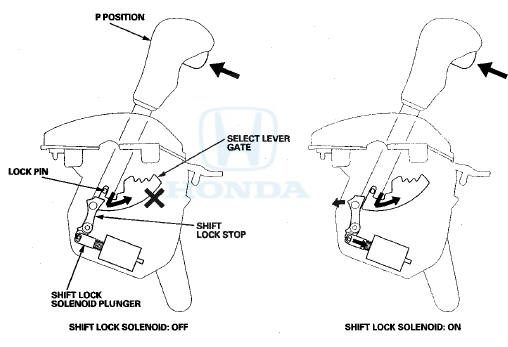
*: This illustration shows the Type B shift lever.
When the shift lock system does not operate due to a mechanical or electrical problem, you can unlock the shift lock temporarily by inserting the ignition key into the shift lock release hole and press the shift lock release. When the shift lock release is pressed, the shift lock stop releases the lock pin, and the shift lever can move to any other position.
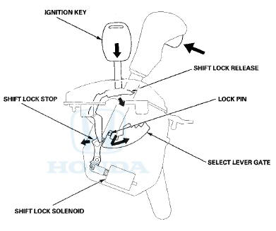
*: This illustration shows the Type B shift lever.
Circuit Diagram - PCM A /T Control S f stem
Circuit Diagram - PCM A/T Control System (cont'd)

 DTC Troubleshooting
DTC P062F: Powertrain Control Module (PCM)
Internal Control Module Keep Alive Memory
(KAM) Error
NOTE: Before you troubleshoot record all freeze data
and any on-board snapshot with the HDS, and re ...
See also:
Playing a CD
Your audio system supports audio CDs, CD-Rs and CD-RWs in either MP3, WMA, or
AAC*1 format. With the CD loaded, select the CD mode.
• How to Select a File from the Music Search List
(MP3/WMA/ ...
Glove Box Lock Cylinder Replacement
NOTE: Take care not to scratch the glove box.
1. Remove the glove box (see page 20-174).
2. While lifting the glove box handle (A), pull out one
end of the retainer (B) with a hook-shaped tool ...
Vehicle Identification Number
Manufacturer, Make, and Type of Vehicle
1HG: Honda of America Mfg., inc.
Honda passenger vehicle .
JHM: Honda Motor Co., Ltd.
Honda passenger vehicle
Line, Body, and Engine Type
CP2: Accor ...