 Honda Accord: Symptom Troubleshooting
Poor ASH or FM radio reception or interference
NOTE: • Check the vehicle battery condition first (see page 22-90).
• Check the connectors for poor connections or loose terminals.
• Check for aftermarket accessories including cell phones and chargers plugged into the vehicle accessory power sockets.
• Check the radio reception in an open area. Poor reception/interference can be caused by any of these conditions: - The radio station is far away.
- Atmospheric conditions are unfavorable.
- Aftermarket metallic window tint.
- A tall building, mountains, or high-voltage power lines are nearby.
1. Turn the ignition switch to ON (II).
2. Do the Seek Stop Test (see page 23-114), and the reception level indication in the Self-diagnostic Function (see page 23-57).
Is the test vehicle within 10 % of the known-good vehicle? YES
-Multipath interference or weak station.
Operation is normal.
NO
-Go to step 3.
3. Check the reception/interference is the same in several locations.
Is the reception/interference the same? YES
-Go to step 4.
NO
-Multipath interference or weak station. Operation is normal.H 4. Check the reception/interference while the engine is running.
Is there noise (static or whine) only with the engine running? YES
-Check the antenna and radio grounds. If OK, check the charging system and the ignition s y s t e m . N O
- G o to step 5.
5. Turn the ignition switch to LOCK (0).
6. Remove the right C-pillar trim (see page 20-110).
7. Check the connections from the AM/FM antenna amplifier to the window antenna.
Are there any loose or damaged connections? YES
-Repair the connections, or substitute a known-good AM/FM antenna amplifier (see page 23-125), and retest. If the symptom/condition goes away, replace the original AM/FM antenna amplifier.
N O
- G o to step 8.
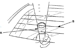
8. With the help of an assistant inside the vehicle, have the assistant shine a strong flashlight (A) along each antenna wire (B). Check from the outside of the vehicle for any breaks or openings in the antenna wires (the light shines through any breaks or cuts).
NOTE: It is easier to see the breaks if you do this test in a dark or shaded area.
Are there any breaks or cuts in the antenna? YES-
Repair the window antenna. Go to AM/FM antenna repair (see page 23-126), or replace the rear window (see page 20-75) if the damaged section is too long.
N O
- Go to step 9.
9. Disconnect the AM/FM antenna amplifier 3P connector (see page 23-125).
10. Turn the ignition switch to ON (II).
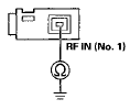
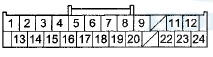
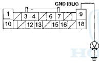
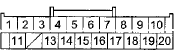
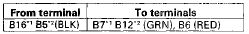
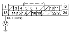
11 Measure the voltage between the AM/FM antenna amplifier 3P connector terminal No. 3 and body ground.
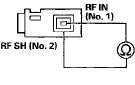
AM/FM ANTENNA AMPLIFIER 3P CONNECTOR
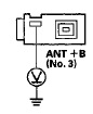
Terminal side of female terminals
Is there battery voltage? YES
-Go to step 17.
NO
-Goto step 12.
12. Turn the ignition switch to LOCK (0).
13. Remove the audio unit.
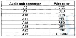
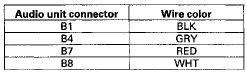
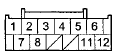
• With navigation (see page 23-114) • Without navigation (see page 23-115) 14. Disconnect audio unit connector F (3P).
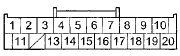
15. Check for continuity between audio unit connector F (3P) terminal No. 3 and the AM/FM antenna amplifier 3P connector terminal No. 3.
AUDIO UNIT CONNECTOR F (3P)
Terminal side of female terminals
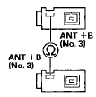
AM/FM ANTENNA AMPLIFIER 3P CONNECTOR
Terminal side of female terminals
Is there continuity? YES
-Go to step 16.
NO
-Repair an open in the wire between the audio unit and the AM/FM antenna amplifier. Also check the AM/FM antenna lead/sublead connector.
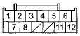
16. Check for continuity between audio unit connector F (3P) terminal No. 3 and body ground.
AUDIO UNIT CONNECTOR F (3P)

Terminal side of female terminals
Is there continuity? YES
-Repair a short to body ground in the wire between the audio unit and AM/FM antenna amplifier.
NO
-Replace the audio unit.
• With navigation (see page 23-114) • Without navigation (see page 23-115) 17. Remove the audio unit.
• With navigation (see page 23-114) • Without navigation (see page 23-115) 18. Disconnect audio unit connector F (3P).
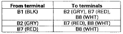
1 9 . Check for continuity between audio unit connector F (3P) terminal No. 1 and the AM/FM antenna amplifier 3P connector terminal No. 1 .
AUDIO UNIT CONNECTOR F (3P)
Terminal side of female terminals
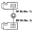
AM/FM ANTENNA AMPLIFIER 3P CONNECTOR
Terminal side of female terminals
Is there continuity? YES
-Go to step 20.
NO
-Replace the AM/FM antenna lead and/or sublead.
20. Check for continuity between audio unit connector F (3P) terminal No. 1 and body ground.
AUDIO UNIT CONNECTOR F (3P)
Terminal side of female terminals
Is there continuity? YES
-Replace the AM/FM antenna lead and/or sublead.
NO-
Go to step 21.
21. Check for continuity between audio unit connector F (3P) terminal No. 2 and the AM/FM antenna amplifier 3P connector terminal No. 2.
AUDIO UNIT CONNECTOR F (3P)
Terminal side of female terminals
AM/FM ANTENNA AMPLIFIER 3P CONNECTOR
Terminal side of female terminals
Is there continuity? YES
-Go to step 22.
NO
-Replace the AM/FM antenna lead and/or sublead.
22. Check for continuity between audio unit connector F (3P) terminals No. 1 and No. 2.
AUDIO UNIT CONNECTOR F (3P)
Terminal side of female terminals
Is there continuity? YES
-Replace the AM/FM antenna lead and/or sublead.
NO
-Replace the AM/FM antenna amplifier (see page 23-125) and recheck. If the reception still poor, replace the audio unit.
• With navigation (see page 23-114) • Without navigation (see page 23-115)
Audio unit power switch will not turn on (No information display and- no sound)
NOTE: • Check the vehicle battery condition first (see page 22- 90).
• Check the connectors for poor connections or loose terminals.
1. Turn the ignition switch to ON (II).
2. Push the power switch ON to see if audio unit turns ON.
Does the audio unit display operate properly, and does the audio unit sound normal? YES
-lntermittent failure, the system is OK at this time.
NO
-Go to step 3.
3. Turn the ignition switch to LOCK (0).
4. Check the No. 15 (10 A) fuse in the under-hood fuse/ relay box and the No. 18 (7.5 A) fuse in the driver's under-dash fuse/relay box.
Are the fuses OK? YES
-Go to step 5.
NO
-Replace the fuse, and recheck.
5. Remove the audio unit with navigation (see page 23- 114), without navigation (see page 23-115). Check that the audio unit connectors are properly connected.
Are they connected properly? YES
-Go to step 6.
NO
-Repair poor connections and reconnect the connectors, and recheck the function.
6. Turn the ignition switch to ON (II).
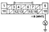
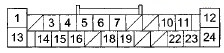
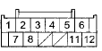
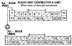
7. Measure the voltage between body ground and audio unit connector A (24P) terminals No. 14 and No. 24 individually.
AUDIO UNIT CONNECTOR A (24P)
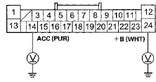
Wire side of female terminals
Is there battery voltage? YES
-Go to step 8.
NO
-Repair an open in the wire(s) between the No, 15 (10 A) fuse in the under-hood fuse/relay box, the No. 18 (7.5 A) fuse in the driver's under-dash fuse/relay box and the audio unit.
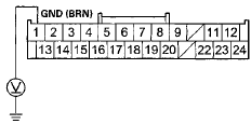
8. Measure the voltage between audio unit connector A (24P) terminal No. 12 and body ground.
AUDIO UNIT CONNECTOR A (24P)
Wire side of female terminals
Is there less than 0.2 V? YES-
Replace the audio unit.l • With navigation (see page 23-114) • Without navigation (see page 23-115) NO
-Repair an open or high resistance in the wire between the audio unit connector A (24P) terminal No. 12 and body ground (G402) (see page 22-40).
Audio unit power switch will not turn off
NOTE: • Check the vehicle battery condition first (see page 2 2 - 9 0 ) .
• Check the connectors for poor connections or loose terminals.
• Check for aftermarket accessories plugged into the vehicle's accessory power sockets.
1. Turn the ignition switch to ON (II).
2. Push the power switch off or turn the ignition switch to LOCK (0) to see if the audio unit turns off.
Does the audio unit turn off? YES
-Go to step 3.
NO
-Replace the audio u n i t .l • With navigation (see page 23-114) • Without navigation (see page 23-115) 3. Turn the ignition switch to ON (II), push the power switch on, then turn the ignition switch to LOCK (0).
Does the audio unit turn off? YES
-Operation is normal .
NO
-Go to step 4.
4. Remove the audio unit with navigation (see page 23- 114), without navigation (see page 23-115).
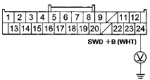
5. Measure the voltage between audio unit connector A (24P) terminal No. 14 and body ground.
AUDIO UNIT CONNECTOR A (24P)
Wire side of female terminals
Is there battery voltage? YES
-Check for a short to power on the PUR wire.
NO
-Replace the audio u n i t .
• With navigation (see page 23-114) • Without navigation (see page 23-115)
No sound is heard from the speaker(s) (display is normal) (with premium audio)
NOTE: • Check the vehicle battery condition first (see page 22-90).
• Check the connectors for poor connections or loose terminals.
• Set the fader and balance positions to the center.
• Before doing the troubleshooting, do the Audio unit power switch will not turn on troubleshooting (see page 23-69).
1. Turn the ignition switch to ON (II).
2. Turn on the audio unit, and make sure the volume button is not set to the MIN level.
Is it at the MIN level? YES
-Raise the volume level, and recheck the function.
NO
-Go to step 3.
3. On the steering wheel, check the navigation talk command, and/or the HandsFreeLink talk command function.
Are the navigation talk command and/or the HFL talk command function set? YES
-Cancel the navigation talk command by pressing the navigation BACK button, and/or HFL talk command, press the HFL BACK button, then recheck the function.
NO
-Go to step 4 .
4. Do the speaker check mode with the Self-diagnostic Function (see page 23-58).
Do all speakers produce a tone? YES
-System is OK at this time. Check for poor connections at the audio unit, speakers and stereo amplifier.
NO
-Go to step 5.
5. Turn the ignition switch to LOCK (0).
6. Check the No. 15 (20 A) fuse in the passenger's under-dash fuse/relay box, the No. 15 (10 A) fuse in the under-hood fuse/relay box, and the No. 18 (7.5 A) fuse in the driver's under-dash fuse/relay box.
Are the fuses OK? YES
-Go to step 7.
NO
-Replace the fuse(s), and recheck.
7. Check the speaker(s) with no sound for any damage.
Is there any damage? YES
-Replace the speaker (see page 23-122) and recheck.
NO
-Go to step 8.
8. Remove the speaker(s) with no sound (see page 23-122), and disconnect its connector.
9. Check the speaker 2P connector for a loose or poor connection.
Reconnect the speaker connector, and recheck the symptom; is the condition still present? YES
-Go to step 10.
NO
-lntermittent failure. Operation is normal.
10. Test the speaker(s) (see page 23-122).
Is the speaker OK? YES
-Go to step 11.
NO
-Replace the speaker(s) (see page 23-122).
11 . Reconnect the speaker connector(s).
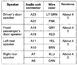
12. Disconnect stereo amplifier connector B (18P) and the door speaker crossover network control unit 8P connectors.
13. Check for continuity between body ground and stereo amplifier connector B (18P) and between body ground and the door speaker crossover network control unit 8P connector according to the table.
STEREO AMPLIFIER CONNECTOR B (18P)
Wire side of female terminals
SPEAKER CROSSOVER NETWORK CONTROL UNIT CONNECTOR (SP)

Wire side of female terminals
Is there continuity? YES
-Repair a short to body ground in the wire(s) between the stereo amplifier and the door speaker crossover network control unit, or the door speaker crossover network control unit and the speaker(s).u NO
-Go to step 14.
14. Measure the resistance between each pair of speaker terminals at stereo amplifier connector A (18P) and the speaker crossover network control unit according to the table.
STEREO AMPLIFIER CONNECTOR B (18P)
Wire side of female terminals
SPEAKER CROSSOVER NETWORK CONTROL UNIT CONNECTOR (8P)

Wire side of female terminals
is the resistance OK? YES
-Go to step 15.
NO
-Repair an open or a short in the wire between the stereo amplifier and the speaker.
15. Disconnect audio unit connector A (24P), stereo amplifier connector A (24P), and audio unit connector D (8P).
NOTE: Eject all the CDs before disconnecting the audio unit and CD changer to prevent damaging the CD player's load mechanism.
16. Check for continuity between audio unit connector A (24P), connector D (8P) and stereo amplifier connector A (24P) according to the table.
AUDIO UNIT CONNECTOR A (24P)
Wire side of female terminals
AUDIO UNIT CONNECTOR D ( S P )

Wire side of female terminals
STEREO AMPLIFIER CONNECTOR A (24P)
Wire side of female terminals
Is there continuity? YES
-Go to step 17.
NO
-Repair a n open i n the applicable wire(s) between the audio unit a n d stereo amplifier (replace the affected shielded harness).
17. Check for continuity between stereo amplifier connector A (24P) and body ground according to the table.
STEREO AMPLIFIER CONNECTOR A (24P)
Wire side of female terminals
Is there continuity? YES
-Repair a short to body ground in the wire(s) between the audio unit and stereo amplifier (replace the affected shielded harness).
NO
-Go to step 18.
18. Reconnect stereo amplifier connector A (24P) and B (18P).
19. Measure the voltage between stereo amplifier connector B (18P) terminal No. 18 and body ground.
STEREO AMPLIFIER CONNECTOR B (18P)
Wire side of female terminals
Is there battery voltage? YES
-Go to step 20.
NO
-Repair an open in the wire between the No. 15 (20 A) fuse in the passenger's under-dash fuse/relay box and stereo amplifier connector B (18P) terminal No. 18 . 20. Turn the ignition switch to ON (II).
21. Measure the voltage between stereo amplifier connector A (24P) terminal No. 24 and body ground.
STEREO AMPLIFIER CONNECTOR A (24P)
Wire side of female terminals
Is there battery voltage? YES-
Go to step 22.
NO
-Repair an open in the wire between stereo amplifier connector A (24P) terminal No. 24 and audio unit connector A (24P) terminal No. 17.
22. Measure the voltage between stereo amplifier connector A (24P) terminal No. 1 and body ground, and between stereo amplifier connector B (18P) terminal No. 9 and body ground.
STEREO AMPLIFIER CONNECTOR A (24P)
Wire side of female terminals
STEREO AMPLIFIER CONNECTOR B (18P)
Wire side of female terminals
Is there less than 0.2 V? YES
-Go to step 23.
NO-
Repair an open or high resistance in the wire between stereo amplifier connector A (24P) terminal No. 1, connector B (18P) terminal No. 9 and body ground (G401, G402) (see page 22-40).
23. Substitute a known-good door speaker crossover network control unit (see page 23-121), and recheck.
Is the symptom still present? YES
-Substitute a known-good audio unit with navigation (see page 23-114), without navigation (see page 23-115), and recheck. If the symptom/ indication goes away, replace the original audio unit. If the symptoms still present, substitute a known-good stereo amplifier (see page 23-119), and recheck. If the symptom/indication goes away, replace the original stereo amplifier.
NO
-Replace the original door speaker crossover network control unit (see page 23-121).
No Sound is heard from the speaker(s) (display is normal) (without premium audio)
NOTE: • Check the vehicle battery condition first (see page 22-90).
• Check the connectors for poor connections or loose terminals.
• Set the fader and balance positions to the center.
• Before doing symptom troubleshooting, do the audio unit power switch will not turn on troubleshooting (see page 23-69).
1. Turn the ignition switch to ON (II).
2. Turn on the audio unit and make sure the volume button is not set to the MIN level.
Is it at the MIN level? YES
-Raise the volume level, and recheck the function.
NO
-Go to step 3.
3. Go to the speaker check mode in the audio system Self-diagnostic Function (see page 23-58).
Do all speakers produce a tone? YES
-lntermittent failure; the system is OK at this time.
Check for poor connections at the audio unit and speakers.
NO
-Go to step 4.
4. Turn the ignition switch to LOCK (0).
5. Check the speaker(s) with no sound for any damage.
Is there any damage? YES-
Substitute the speaker (see page 23-122) and recheck.
NO
-Go to step 6.
6. Check the speaker 2P connector for a loose or poor connection.
Reconnect the speaker connector, and recheck the symptom; is the condition still present? YES
-Go to step 7.
NO-
lntermittent failure. Operation is normal.
7. Test the speaker(s) (see page 23-122).
Is the speaker OK? YES
-Go to step 8.
NO
-Replace the speaker(s) (see page 23-122).
8. Reconnect the speaker connector(s).
3. Disconnect audio unit connector A (24P).
NOTE; Eject all the CDs before removing the'audio unit and CD changer to prevent damaging the CD player's load mechanism.
10. Check for continuity between audio unit connector A (24P) and body ground according to the table.
AUDIO UNIT CONNECTOR A (24P)
Wire side of female terminals
Is there continuity? YES
-Repair a short to body ground in the wire(s) between the audio unit and the speaker(s).
NO
-Go to step 11.
11. Disconnect the tweeter 2P connectors.
12. Measure the resistance between each pair of speaker terminals at audio unit connector A (24P) according to the table.
AUDIO UNIT CONNECTOR A (24P)
Wire side of female terminals
Is the resistance OK? YES
-Go to step 13.
NO
-Repair an open or a short in the wire between the audio unit and the speaker(s).! 13. Disconnect the door speaker 2P connectors.
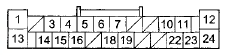
14. Connect audio unit connector A (24P) terminals with a jumper wire as shown.
AUDIO UNIT CONNECTOR A (24P)
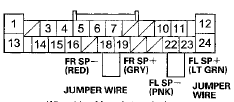
Wire side of female terminals
15. Check for continuity between the tweeter 2P connector according to the table.
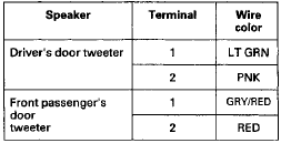
DRIVER'S DOOR TWEETER 2P CONNECTOR
FRONT PASSENGERES DOOR
TWEETER 2P CONNECTOR

Wire side of female terminals
Is there continuity? YES
-Replace the audio unit (see page 23-115).
NO
-Repair an open in the wire between the audio unit and the tweeter.
Auxilialry input sound is low or cannot be heard
NOTE: • Check the vehicle battery condition first (see page 22-90).
• Check the connectors for poor connections or loose terminals.
• Use auxiliary stereo cables with 3.5 mm ends only.
• Auxiliary accessories may be played on the audio unit using the auxiliary input. - 1. Turn the ignition switch to ON (II).
2. Turn the audio unit and connect an auxiliary accessory to the auxiliary input jack.
3. Check the volume operation.
Is the sound normal? YES
-Operation is normal at this time.
NO
-Go to step 4.
4. Make sure auxiliary accessory volume is set to high.
Is the volume set to high? YES
-Go to step 5.
NO
-Raise the auxiliary accessory volume to high.
Make sure the audio unit volume is turned down before retesting.H 5. Substitute a known-good auxiliary audio accessory and/or auxiliary stereo cable, and recheck.
Does the auxiliary audio accessory operate properly? YES
-Original auxiliary audio accessory or auxiliary stereo cable is faulty.
NO
-Go to step 6.
6. Turn the ignition switch to LOCK (0).
7. Remove the auxiliary jack assembly (see page 23-127) and check that the auxiliary jack assembly is properly connected.
Is the auxiliary jack assembly connected properly? YES-
• Except 1 CD type: go to step 8.
• 1 CD type: go to step 13.
NO
-Reconnect the connector, and recheck the function.
8. Disconnect the auxiliary jack assembly 5P connector.
9. Disconnect audio unit connector B (20P).
10. Check for continuity between body ground and audio unit connector B (20P) according to the table.
AUDIO UNIT CONNECTOR B (20P)
Wire side of female terminals
Is there continuity? YES
-There is a short to body ground in the wire(s) between the audio unit and the auxiliary jack assembly. Replace the affected shielded harness.
NO
-Go to step 11.
11. Check for continuity between audio unit connector B (20P) according to the table.
AUDIO UNIT CONNECTOR B (20P)
Wire side of female terminals
Is there continuity? YES
-There is a short in the wire(s) between the audio unit and the auxiliary jack assembly. Replace the affected shielded harness.
NO
-Go to step 12.
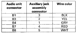
12. Check for continuity between audio unit connector B (20P) and the auxiliary jack assembly 5P connector according to the table.
AUDIO UNIT CONNECTOR B (20P)
Wire side of female terminals
AUXILIARY JACK ASSEMBLY 5P CONNECTOR

Wire side of female terminals
Is there continuity? YES
-Substitute a known-good auxiliary jack assembly (see page 23-127), and recheck. If the symptom/indication goes away, replace the original auxiliary jack assembly. If the symptom/indication is still present, replace the audio unit with navigation (see page 23-114), without navigation (see page 23-115).
NO
-There is an open in the wire(s) between the audio unit and the auxiliary jack assembly. Replace the affected shielded harness.
13. Disconnect the auxiliary jack assembly 5P connector.
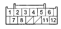
14. Disconnect audio unit connector B (12P).
15. Check for continuity between body ground and audio unit connector B (12P) according to the table.
AUDIO UNIT CONNECTOR B (12P)
Wire side of female terminals
Is there continuity? YES
-The re is a short to body ground in the wire(s) between the audio unit and the auxiliary jack assembly. Replace the affected shielded harness.
NO
-Go to step 16.
16. Check for continuity between audio unit connector B (12P) according to the table.
AUDIO UNIT CONNECTOR B (12P)
Wire side of female terminals
Is there continuity? YES
-The re is a short in the wire(s) between the audio unit and the auxiliary jack assembly. Replace the affected shielded harness.
NO
-Goto step 17.
17. Check for continuity between audio unit connector B (12P) and auxiliary jack assembly 5P connector according to the table.
AUDIO UNIT CONNECTOR B (12P)
Wire side of female terminals
AUXILIARY JACK ASSEMBLY SP CONNECTOR

Wire side of female terminals
Is there continuity? YES
-Substitute a known-good auxiliary jack assembly (see page 23-127), and recheck. If the symptom/indication goes away, replace the original auxiliary jack assembly. If the symptom/indication is still present, replace the audio unit with navigation (see page 23-114), without navigation (see page 23-115).
NO
-There is an open in the wire(s) between the audio unit and the auxiliary jack assembly. Replace the affected shielded harness.
Audio s f stem sound is weak or distorted (display is normal)
NOTE; • Check the vehicle battery condition first (see page 22-90).
• Check the connectors for poor connections or loose terminals.
1. Turn the ignition switch to ON (II).
2. Turn on the audio unit, and check for sound In each mode (AM, FM, XM, and CD).
Is there sound from the speakers, and Is the sound quality normal in each mode? YES
-lntermittent failure. The system is OK at this time. Check for loose connections at the audio unit, the amplifier, and each speaker.! NO
-Speakers all work, sound quality is p o o r . ! • If sound quality is poor only with the XM radio, or the XM radio does not function, go to Poor or no sound with XM radio (see page 23-109).
• If the sound quality is poor only with AM or FM, go to Poor AM or FM radio reception or interference (see page 23-66).
• If the sound is poor in all modes, go to Sound Quality Diagnosis (see page 23-110).
Radio preset memory is lost
NOTE: If only XM stations are lost, go to XM radio preset memory is lost (see page 23-108).
1. Turn the ignition switch to ON (II).
2. Turn on the audio unit and set each of the radio station preset buttons.
Do each of the buttons set properly? YES
-Go to step 3.
NO
-Replace the audio u n i t.
• With navigation (see page 23-114) • Without navigation (see page 23-115) 3. Turn the ignition switch to LOCK (0) for 1 minute, then w n it back to ON (II).
4. Test the preset buttons for proper recall operation.
Do the preset buttons recall the set radio stations? YES
-System is normal at this time. Check connections at the audio u n i t .
NO
-Substitute a known-good audio unit with navigation (see page 23-114), without navigation (see page 23-115), and recheck. If the symptom/indication goes away, replace the original audio unit
Volume does not change
NOTE: • Check the vehicle battery condition first (see page 22-90).
• Check the connectors for poor connections or loose terminals.
• Set the fader and the balance positions to the center.
1. Turn the ignition switch to ON (II).
2. Turn on the audio unit, and check for sound in each mode (AM, FM, XM, and CD).
Is the sound normal? YES
-Go to step 3.
NO
-Go to Sound Quality Diagnosis (see page 23-110) or No sound is heard from the speaker(s) with premium audio system (see page 23-70), without premium audio system (see page 23-75).
3. Operate the volume knob to see if the volume changes.
Does the volume change? YES
-Operation is normal.
NO
-Substitute a known-good audio unit with navigation (see page 23-114), without navigation (see page 23-115), and recheck. If the symptom/indication goes away, replace the original audio unit.
Volume does not increase w i t h speed
NOTE: • Check the vehicle battery condition first (see page . 22-90).
• Check the connectors for poor connections or loose terminals.
1. Test-drive the vehicle at highway speeds, and monitor if the volume increases.
Does the volume increase? YES
-lntermittent failure, the system is OK at this time.
NO
-Go to step 2.
2. Verify SVC mode setting in audio unit sound adjustment set-up.
Is the SVC set to off? YES-Change setting to MID, and retest.
NO-Go to step 3.
3. Do the Self-diagnostic Function for the vehicle speed pulse indication (see page 23-54).
Does self-diagnostic function indicate a VSP signal? YES
-Substitute a known-good audio unit with navigation (see page 23-114), without navigation (see page 23-115), and retest. If the symptom/indication goes away, replace the original audio unit.
NO
- • 1 CD type: Go to step 4.
• Except 1 CD type: Check for B-CAN DTCs (communication BUS Line Error) with the HDS and go to the indicated DTCs troubleshooting. If no B-CAN DTCs or communication bus line errors are found, substitute a known-good audio unit with navigation (see page 23-114), without navigation (see page 23-115), and recheck. If the symptom goes away, replace the original audio unit.
4. Remove the audio unit with navigation (see page 23-114), without navigation (see page 23-115), and disconnect audio unit connector A (24P).
NOTE: Eject all the CDs before removing the audio unit and CD changer to prevent damaging the CD player's load mechanism.
5. Turn the ignition switch to ON (II).
6. Test-drive the vehicle and have an assistant measure the voltage at audio unit connector A (24P) terminal No. 15.
NOTE: Some volt meters may show an average of 2.5 V, and others may show a constant voltage, depending on the meter's measurement speed.
AUDIO UNIT CONNECTOR A (24P)
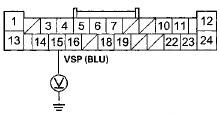
Wire side of female terminals
Is there a 0—5 Vpulse? YES
-Substitute a known-good audio unit with navigation (see page 23-114), without navigation (see page 23-115), and recheck. If the symptom/indication goes away, replace the original audio unit.
NO-
Repair opens or shorts in the wire between the audio unit connector A (24P) terminal No. 15 and the ECM/PCM connector A (49P) terminal No. 30. If no opens are found, update the ECM/PCM (see page 11-203), if it does not have the latest software or substitute a known-good ECM/PCM (see page 11-204).
Volume is too high or too low when driving at freeway speeds
NOTE: • Check the vehicle battery condition first (see page 22-90).
• Check the connectors for poor connections or loose terminals.
1. Test-drive the vehicle at highway speeds, and monitor volume level.
Is the volume level too high, or too low? YES
-Go to step 2.
NO
-lntermittent failure, the system is OK at this time.
2. Change SVC mode setting in sound adjustment set-up to Mid, and retest.
Is the volume level still too high or too low? YES-Substitute a known-good audio unit with navigation (see page 23-114), without navigation (see page 23-115), and recheck. If the symptom/indication goes away, replace the original audio unit.
NO-lmproper SVC setting for customer's sound taste.
Radio tuner does not change stations
NOTE: • Check the vehicle battery condition first (see page 22- 90).
• Check the connectors for poor connections or loose terminals.
1. Turn the ignition switch to ON (II).
2. Turn on the audio unit, and note the audio information on the display panel.
Does the audio information display properly? YES
-Go to step 3.
NO
-Go to Audio system information does not display on the audio-HVAC (sub) display unit (see page 23- 83).
3. Operate the tuning knob to see if the radio station changes.
Does the radio station change? YES
-lntermittent failure, the tuning knob is OK at this time.
NO
-Go to step 4.
4. Go to the audio button, knob, and remote switch detection mode in the audio system Self-diagnostic Function (see page 23-54).
Is the rotating portion of the selector knob (tune (sound) knob ICD) detected when operated in both directions? YES
-Substitute a known-good audio unit with navigation (see page 23-114), without navigation (see page 23-115), and recheck. If the symptom/indication goes away, replace the original audio unit.
NO
-Substitute a known-good audio switch panel, and recheck. If the symptom/indication goes away, replace the original audio switch panel (see page 23-117). If the system is still present, substitute a known-good audio unit with navigation (see page 23-114), without navigation (see page 23-115) and recheck. If the symptom/indication goes away, replace the original audio unit.
Audio system information does not display on the audio-HVAC (sub) display unit
NOTE: • Check the vehicle battery condition first (see page 22- 90).
• Check the connectors for poor connections or loose terminals.
1. Remove the audio-HVAC display unit (see page 23- 119).
2. Check the connections at the audio-HVAC (sub) display unit 12P connector and audio unit connector B (20P).
Are the connectors and terminals connected properly? YES
-Go to step 3.
NO
-Repair the connection, and recheck.
3. Turn the ignition switch to ON (II).
4. Measure the voltage between audio-HVAC (sub) display unit 12P connector terminal No. 6 and body ground.
AUDIO-HVAC (SUB) DISPLAY UNIT 12P CONNECTOR
Wire side of female terminals
Is there battery voltage? YES
-Go to step 5.
NO
-Repair an open in the wire between the No. 15 (10 A) fuse in the under-hood fuse/relay box and audio-HVAC (sub) display unit 12P connector terminal No. 6.
6. Measure the voltage between the audio-HVAC (sub) display unit 12P connectorterminal No. i and body ground.
AUDIO-HVAC (SUB) DISPLAY UNIT 12P CONNECTOR
Wire side of female terminals
Is there less than 0.2 V? YES
-Go to step 6.
NO
-Repair an open or high resistance in the wire between audio-HVAC (sub) display 12P connector terminal No. 9 and body ground (G402) (see page 22-40).
6. Turn the ignition switch to LOCK (0).
7. Disconnect audio unit connector B (20P) and the audio-HVAC (sub) display unit 12P connector.
8. Check for continuity between audio unit connector B (20P) (except 1 CD type) or B (12P) (1 CD type) and the audio-HVAC (sub) display unit 12P connector according to the table.
*1: Except 1 CD type
*2:1 CD type
Except 1 CD type
AUDIO UNIT CONNECTOR B (20P)
Wire side of female terminals
1 CD type
AUDIO UNIT CONNECTOR B (12P)
Wire side of female terminals
AUDIO-HVAC (SUB) DISPLAY UNIT 12P CONNECTOR
Wire side of female terminals
Is there continuity? YES
-Go to step 9.
NO-
Repair an open in the wire(s) between the audio unit and the audio-HVAC (sub) display unit (replace the affected shielded harness.
9. Check for continuity between the terminals of the audio-HVAC (sub) display unit 12P connector and body ground according to the table.
AUDIO-HVAC (SUB) DISPLAY UNIT 12P CONNECTOR
Wire side of female terminals
Is there continuity? YES-
Repair a short to body ground in the wire(s) between the audio unit and the audio-HVAC (sub) display unit (replace the affected shielded harness).
NO
-Goto step 10.
10. Check for continuity between the terminals of audio unit connector B (20P) (except 1 CD type) or B (12P) (1 CD type) according to the table.
*1: Except 1 CD type
*2:1 CD type
Except 1 CD type
AUDIO UNIT CONNECTOR B (20P)
Wire side of female terminals
1 CD type
AUDIO UNIT CONNECTOR B (12P)
Wire side of female terminals
Is there continuity between any of the terminals? YES
-Repair a short in the wire(s) between the audio unit and the audio-HVAC (sub) display unit (replace the affected shielded harness).
NO
-Substitute a known-good audio-HVAC (sub) display unit (see page 23-119), and recheck. If the symptom/indication goes away, replace the original audio-HVAC (sub) display unit. If the symptom is still present, substitute a known-good audio unit with navigation (see page 23-114), without navigation (see page 23-115), and recheck. if the symptom/indication goes away, replace the original a u d i o unit.
Security indicator does not work properly
NOTE: • The system operates without the 5-digit security (anti-theft) code.
• Before troubleshooting, make sure you have the anti-theft code..
1. Turn off the audio system.
Is the security indicator (LED) on (blink)? YES-Go to Step 2.
NO-Substitute a known-good audio unit with navigation (see page 23-114), without navigation (see page 23-115), and recheck. If the symptom/indication goes away, replace the original audio unit. If the symptom is still present, substitute a known-good audio switch panel (see page 23-117), and recheck. if the symptom/indication goes away, replace the original audio switch panel.
2. Turn on the audio system.
Is the security indicator (LED) out? YES
-The audio unit is OK at this time. Check for loose or poor connections at the audio unit and the audio panel.
NO
-Substitute a known-good audio unit with navigation (see page 23-114), without navigation (see page 23-115), and recheck. If the symptom/indicated goes away, replace the original audio unit. If the symptom is still present, substitute a known-good audio switch panel (see page 23-117), and recheck. If the symptom/indicated goes away, replace the original audio switch panel.
Audio unit button illumination does not work (1 CD type)
NOTE: • Check the vehicle battery condition first (see page 22-90).
• Check the connectors for poor connections or loose terminals.
1. Turn the ignition switch to ON (II).
2. Turn the combination lighting switch to the parking light position.
3. Check the illumination of the audio unit buttons.
Are the buttons illuminated?
YES
-lntermittent problem; the audio unit is OK at this u £ . Check for loose or poor connections at audio unit connector A (24P).
NO
-Go to step 4.
4. Check the illumination of several other buttons not related to the audio system.
Are the buttons illuminated? YES
-Go to step 5.
NO-
Troubleshoot the interior lights. Start by checking the No. 6 (7.5 A) fuse in the passenger's under-dash fuse/relay box. If the fuse is OK, check for an open in the wire between the passenger's under-dash fuse/relay box and audio unit.
5. Turn the ignition switch to LOCK (0).
6. Disconnect audio unit connector A (24P).
NOTE: Eject all the CDs before removing the audio unit and CD changer to prevent damaging the CD player's load mechanism.
7. Disconnect the gauge control module 32P connector (see page 22-351).
8. Check for continuity between audio unit connector A (24P) terminal No. 1 and gauge control module 32P connector terminal No. 1.
GAUGE CONTROL MODULE 32P CONNECTOR
Wire side of female terminals
Is there continuity? YES
-Go to step 9.
NO
-Repair an open in the wire between the gauge control module and the audio unit.
9. Turn the ignition switch to ON (II).
10. With the headlight switch still on, measure the voltage between audio unit connector A (24P) terminal No. 13 and body ground.
AUDIO UNIT CONNECTOR A (24P)
Wire side of female terminals
Is there battery voltage? YES
-Check the connections at the audio unit connector A (24P). If all connections are OK, substitute a known-good audio unit with navigation (see page 23-114), without navigation (see page 23-115), and recheck. If the symptom/indication goes away, replace the original audio unit. If the symptom is still present, substitute a known-good audio switch panel (see page 23-117), and recheck. If the symptom/indication goes away, replace the original audio switch p a n e l . NO
-Repair an open in the wire between the passenger's under-dash fuse/relay box and the audio unit.
Audio unit button illumination does not work (Except 1 CD type
NOTE; • Check the vehicle battery condition first (see page 22-90).
• Check the connectors for poor connections or loose terminals.
1. Turn the ignition switch to ON (II).
2. Turn the combination lighting switch to the parking light position.
3. Check the illumination of the audio unit buttons.
Are the buttons illuminated? YES
-lntermittent problem; the audio unit is OK at this time.
NO
-Go to step 4.
4. Check the illumination of several other buttons not related to the audio system.
Are the buttons illuminated? YES-
Check for B-CAN DTCs (communication BUS Line Error) with the HDS and go to the indicated DTS's troubleshooting. If no DTCs or communication bus line errors are found, substitute a known-good audio unit with navigation (see page 23-114), without navigation (see page 23-115), and recheck. If the symptom/indication goes away, replace the original audio unit.
NO
-Troubleshoot the interior lights. Start by checking the No. 6 (7.5 A) fuse in the passenger's under-dash fuse/relay box. If the fuse is OK, check for an open in the wire between the passenger's under-dash fuse/relay box and the audio unit.
Audio remote switch does not work properly
NOTE: • Check the vehicle battery condition first (see page 22-90).
e Check the connectors for poor connections or loose terminals.
1. Turn the ignition switch to ON (II).
2. Turn on the audio unit and check the audio unit operation (volume up, volume down, CH (UP), CH (DOWN), MODE).
Is the audio unit operation OK? YES
-Operation is normal.
NO
-Go to step 3.
3. Go to the audio button, knob, and remote switch detection mode in the audio system Self-diagnostic Function (see page 23-54).
Are the remote switch functions detected and functioning properly? YES
-Substitute a known-good audio unit with navigation (see page 23-114), without navigation (see page 23-115), and check. If the symptom/indication goes away, replace the original audio unit.
NO
-Go to step 5.
4. Turn the ignition switch to LOCK (0).
5. Test the audio remote switch (see page 23-125).
Is the audio remote switch OK? YES
-Go to step 6.
NO
-Replace the audio remote switch (see page 17-7).
6. Remove the audio unit.
• With navigation (see page 23-114) • Without navigation (see page 23-115) 7. Disconnect audio unit connector A (24P).
NOTE: Eject all the CDs before disconnecting the audio unit and CD changer to prevent damaging the CD player's load mechanism.
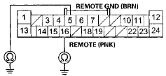
8. Reconnect the audio remote switch, and measure the resistance between the audio unit connector A (24P) terminals No. 5 and No. 16 as specified in the table.
AUDIO UNIT CONNECTOR A (24P)
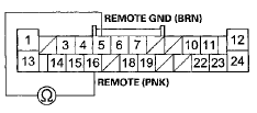
Wire side of female terminals
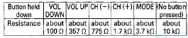
AUDIO REMOTE SWITCH TABLE
Is the resistance OK?
YES
-Go to step 9.
NO
-Repair a short or high resistance in the circuit between the audio unit and the audio remote switch.
If the wires are OK, replace the cable reel (see page 24-225).
9. Check for continuity between body ground and audio unit connector A (24P) terminals No. 5 and No. 16 individually.
AUDIO UNIT CONNECTOR A (24P)
Wire side of female terminals
Is there continuity? YES-Repair a short to body ground in the circuit between the audio unit and the audio remote switch.
If the wires are OK, replace the cable reel (see page 24-225).
NO-Replace the audio unit.
• With navigation (see page 23-114) •Without navigation (see page 23-115)
Audio disc does not load
NOTE: • Check the vehicle battery condition first (see page 22-90).
• Check the connectors for poor connections or loose terminals.
• Disc labels should not be used in the audio unit. They may jam and damage the player mechanism.
• Make sure the audio disc is compatible with the system (see the owner's manual for more information).
1. Turn the ignition switch to ON (II).
2. Turn on the audio unit and insert a known-good disc to see if the symptom can be duplicated.
Does the disc load?
YES-
Operation is normal. If the disc loads normally, but will not play, go to Audio disc does not play (see page 23-92).
NO
-Go to step 3.
3. Insert another disc.
Does the disc load? YES
-The original disc is faulty.
NO
- • With navigation: Substitute a known-good audio disc changer (see page 23-118), and recheck. If the symptom/indication goes away, replace the original audio disc changer.
• Without navigation: Substitute a known-good audio unit (see page 23-115), and recheck. If the symptom/indication goes away, replace the original audio unit.
Audio disc does not eject
NOTE: • Check the vehicle battery condition first (see page 22-90).
• Disc labels should not be used in the audio unit. They may jam and damage the player mechanism.
• Check the connectors for poor connections or loose terminals.
1. Turn the ignition switch to ON (II).
2. Turn on the audio unit.
Does the system turn on? YES
-Go to step 3.
NO
-Go to Audio unit power switch will not turn on (see page 23-69).
3. Check to see if the disc ejects correctly with no binding when you push the EJECT button.
Does the disc eject properly? YES
-Operation is normal.
NO
- • With navigation: Substitute a known-good audio disc changer (see page 23-118), and recheck. If the symptom/indication goes away, replace the original audio disc changer.
• Without navigation: Substitute a known-good audio unit (see page 23-115), and recheck. If the symptom/indication goes away, replace the original audio unit.
Audio disc changer does not load ail six discs
NOTE; • Check t h e vehicle battery condition first (see page 22-90).
• Check the connectors for poor connections or loose terminals.
• Disc labels should not be used in the audio unit. They may jam and damage the player mechanism.
1. Turn the ignition switch to ON (II).
2. Turn on the audio unit, and try loading six discs into the audio unit (in-dash disc changer).
Does the audio unit accept aii six discs? YES
-lntermittent failure, the audio unit is OK at this time.H NO
-Go to step 3.
3. Try loading the disc player with six known-good discs.
Does the audio unit (in-dash disc changer) accept aii six discs? YES
-At least one of the original discs is faulty.!! NO
- With navigation: Substitute known-good audio disc changer (see page 23-118), and recheck. If the symptom/indication goes away, replace the original audio disc changer.
• Without navigation; Substitute known-good audio unit (in-dash disc changer) (see page 23-115), and recheck. If the symptom/indication goes away, replace the original audio unit (in-dash disc changer).
Audio disc changer does not move between discs
NOTE: • Check the vehicle battery condition first (see page 22-90).
• Check the connectors for poor connections or loose terminals.
• Disc labels should not be used in the audio unit. They may jam and damage the player mechanism.
1. Turn the ignition switch to ON (II).
2. Insert six discs into the audio unit (in-dash disc changer), and see if the changer moves between discs.
Does the changer operate normally? YES
-lntermittent failure, the disc changer is OK at this time.
NO
-Go to step 3.
3. Insert six known-good discs into the audio unit.
Does the changer operate normally? YES
-At least one of the original discs is faulty.
NO-
• With navigation: Substitute known-good audio disc changer (see page 23-118), and recheck. If the symptom/indication goes away, replace the original audio disc changer.
• Without navigation: Substitute known-good audio unit (in-dash disc changer) (see page 23-115), and recheck. If the symptom/indication goes away, replace the original audio unit (in-dash disc changer).
Special Tools Required
Diagnostic CD 07AAZ-SDBA100
Audio disc does not play
NOTE: • Check the vehicle battery condition first (see page 22- 90).
• Check the connectors for poor connections or loose terminals.
• Disc labels should not be used in the audio unit. They may jam and damage the player mechanism.
1. Turn the ignition switch to ON (II).
2. Turn on the audio unit, and try loading a disc.
Does the disc load? YES
-Go to step 3.
NO
-Go to Audio disc does not load (see page 23- 90).
3. Insert another disc to see if the symptom can be duplicated.
Does the disc play? YES
-Operation is normal.
NO
-Go to step 4.
4. Insert audio diagnostic CD (T/N 07AAZ-SDBA100) in the audio unit.
Does the disc piay? YES
-The original disc is faulty or has an unreadable format.
N O
- • With navigation: Substitute a known-good audio disc changer (see page 23-118), and recheck. If the.
symptom/indication goes away, replace the original audio disc changer.
• Without navigation: Substitute a known-good audio unit (see page 23-115), and recheck. If the symptom/indication goes away, replace the original audio unit.
Special Tools Required
•Diagnostic CD 07AAZ-SDBA100
•Skip Test CD 07AAZ-SDBA200
• Skip Test CD 07AAZ-SDBA300
Audio disc skips
NOTE: • Check the vehicle battery condition first (see page 22-90).
• Check the connectors for poor connections or loose terminals.
• Disc labels should not be used in the audio unit. They may jam and damage the player mechanism.
1. Confirm the vehicles tires are properly inflated.
2. Cneck trie customer's disc for scratches and fingerprints.
NOTE: The following test should be done with the audio unit bass and treble set to the customer's listening settings. When comparing to known-good vehicles, do the comparison on the same model and trim level.
3. Test-drive the vehicle to identify when the customer's disc skips. The audio diagnostic CD (T/N 07AAZSDBA100) can be used if the customer's CD is not available; use tracks 10—12.
Does the disc skip?
YES
-Go to step 4.
NO
-Operation is normal.
4. Compare the customer's CD that skips to a known-good vehicle under the same conditions.
Does the disc skip in the known-good vehicle under the same conditions? YES
-The disc player operation is normal, the problem is with the customer's disc.
NO
-Go to step 5.
NOTE: Do the following test with vehicle parked and the engine running.
5. Insert the diagnostic skip test CD (T/N 07AAZSDBA300).
Play tracks 2—11, and note on which track number(s) where the disc starts skipping. Do the same test on a known-good vehicle.
Does the disc skip on the same track(s) as the known-good vehicle? YES
-Operation is normal.
NO
-Go to step 6.
6. Insert the diagnostic skip test CD (T/N 07AAZSDBA200).
Play tracks 7 - 11 and tracks 13-15and note on which track number(s) the disc starts skipping. Do the same test on a known-good vehicle.
Does the disc skip on the same track number(s) as the known-good vehicle? YES
-Operation is normal.
NO
- • With navigation: Substitute a known-good audio disc changer (see page 23-118), and recheck. If the symptom/indication goes away, replace the original audio disc changer.
• Without navigation: Substitute a known-good audio unit (see page 23-115), and recheck. If the symptom/indication goes away, replace the original audio unit.
Audio unit button does not work
NOTE: • Check the vehicle battery condition first (see page 22- 90).
• In order to troubleshoot the main power switch, go to Audio unit power switch will not turn on (see page 23- 69).
1. Go to the audio button, knob, and remote switch detection mode in the audio Self-diagnostic Function (see page 23-54). Operate all items in the appropriate switch list.
Switch list
With navigation:
With premium
audio system:
Without premium
audio system:
TITLE, XM, FM/AM, PWR/VOL,
SOUND, CD, AUX, 1-6,
CATEGORY, TUNE, SKIP,
SCAN/A. SEL, MAP/GUIDE,
CANCEL, MENU, AUDIO, 
INFO, SETUP
With premium audio system:
1-6, LOAD, EJECT, FM, AM, XM, CD/AUX, TITLE, CLOCK, SCAN, CATEGORY, PWR, SKIP, A.SEL, RETURN, ENTER, MENU
Without premium audio system:
1-6, EJECT, FM, AM, CD, TUNE/SOUND/CD, AUX, TITLE, CLOCK, SCAN, FOLDER, RDT/RDM, A.SEL, SKIP, PWRA/OL
Are all the items in the appropriate switch list detected? YES-
Operation is normal.
NO-
Substitute a known-good audio unit with navigation (see page 23-114), without navigation (see page 23-115), and recheck. If the symptom/indication goes away, replace the original audio unit. If the symptom is still present, substitute a known-good audio switch panel (see page 23-117), and recheck. If the symptom/indication goes away, replace the original audio switch panel.
Audio unit disc indicator does not work
NOTE: • Check the vehicle battery condition first (see page . 22-90).
• Discs with labels should not be used in the audio unit.
They may jam and damage the player mechanism.
1. Turn on the audio system.
2. Insert a known-good disc or press the EJECT button.
Is the DISC indicator (LED) indicated? YES
-The audio unit is OK at this time. Check for loose
 Error Codes
The audio system can display error codes when a problem is detected with the
audio disc changer, the audio disc, the
XM radio, or the anti-theft code.
CD Error Codes
XM Error Codes
Audio Uni ...
 Sound Quality Diagnosis
Special Tools Required
Diagnostic CD 07AAZ-SDBA100
Use the following tests to check sound quality.
NOTE: Before beginning the following tests, write down
the customer's bass, treble, fader and b ...
See also:
Shifting
To shift from Park to any position,
press firmly on the brake pedal, and
press the release button on the front
of the shift lever, then move the
lever. You cannot shift out of Park
when th ...
Secondary Shaft Bearing
Replacement
Special Tools Required
•Driver Handle, 15 x 135L 07749-0010000
•Attachment, 62 x 68 mm 07746-0010500
1. Remove the set plate bolt, then remove the lock
washer (A) and the bearing set pla ...
Brake System Inspection and Test
Inspect the brake system components listed. Repair or replace any parts that
are leaking or damaged.
Component Inspections:
Brake System Test
Brake pedal sinks/fades when braking
1. Set the pa ...