 Honda Accord: Mode Control Motor Test
'08-09 models with A/T and '10 model with A/T
NOTE; Before testing the motor, check for HVAC DTCs (see page 21-9).
1. Disconnect the 7P connector from the mode control motor.

Incorrectly applying power and ground to the mode control motor will damage it Follow the Instructions carefully.
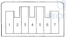
2. Connect battery power to terminal No. 1 of the mode control motor, and ground terminal No. 2; the mode control motor should run smoothly, and stop at Defrost. If it doesn't, reverse the connections; the mode control motor should run smoothly, and stop at Vent. When the mode control motor stops running, disconnect battery power immediately.
MODE CONTROL MOTOR
3. If the mode control motor did not run in step 2, remove it, then check the mode control linkage and doors for smooth movement.
• If the linkage and doors move smoothly, replace the mode control motor (see page 21-62).
• If the linkage or doors stick or bind, repair them as needed.
• If the mode control motor runs smoothly, go to step 4.
4. Use a digital multimeter with an output of 1 mA or less at the 20 kQ range. With the mode control motor running as in step 2, check for continuity between terminal No. 7 and terminals No. 3,4,5, and No. 6 individually. There should be continuity for a moment at each terminal as the motor moves through its travel.
5. If there is no continuity for a moment at each terminal, replace the mode control motor (see page 21-62).
'08-10 .'models with M/T and '08-0S models 2-door with A/T
NOTE: Before testing the motor, check for HVAC DTCs (see page 21-9).
1. Disconnect the 7P connector from the mode control motor.

control motor will damage it Follow the instructions carefully.
2. Connect battery power to terminal No. 1 of the mode control motor, and ground terminal No. 2; the mode control motor should run, and stop at Defrost. If it doesn't, reverse the connections; the mode control motor should run, and stop at Vent. When the mode control motor stops running, disconnect battery power immediately.
MODE CONTROL MOTOR
3. If the mode control motor did not run in step 2, remove it then check the mode control linkage and door for smooth movement.
• If the linkage and door move smoothly, replace the mode control motor (see page 21-62).
• If the linkage or door sticks or binds, repair them as needed.
• If the mode control motor runs smoothly, go to step 4.
4. Measure the resistance between terminals No. 5 and No. 7s of the mode control motor. It should be between 4.2 and 7.8 kO.
5. Reconnect the mode control motor 7P connector, then turn the ignition switch to ON (II).
6. Using the backprobe set, measure the voltage between terminal No. 3 and No. 7 of the 7P connector.
Vent: About 0.5 V
Defrost: About 4.5 V
7. If either the resistance or the voltage readings are not as specified, replace the mode control motor (see page 21-62).
 Air Mix Control Motor Replacement
1. Remove the driver's dashboard undercover (see page
20-170).
2. Disconnect the 7P connector (A) from the air mix
control motor (B). Remove the self-tapping screws
and the air mix control motor ...
 Mode Control Motor Replacement
1. Remove the blower unit (see page 21-65).
2. Disconnect the 7P connector (A) from the mode
control motor (B). Remove the self-tapping screws
and the mode control motor from the heater unit.
...
See also:
Low Fuel Indicator Test
1. Do the gauge self-diagnostic test (see page 22-332).
- If the low fuel indicator flashes, go to step 2.
- If the low fuel indicator does not flash, replace the
gauge control module (see page ...
Transmission Range Switch Test
1. Raise the vehicle on a lift, or apply the parking brake,
block the rear wheels, and raise the front of the
. vehicle. Make sure it is securely supported.
2. Remove the left front wheel.
3. ...
Shift Lock Release, Release Spring, and
Release Shaft Replacement
Type A Shift Lever
1. Remove the shift lever assembly (see page 14-222).
2. Remove the A/T gear position indicator panel from
the shift lever (see page 14-227).
3. Release the lock (A) of the ...