 Honda Accord: MICU Input Test
NOTE: # Before t e s t i n g , t r o u b l e s h o o t the m u l t i p l e x i n t e g r a t e d control unit first, using B-CAN System D i a g n o s i s Test Mode A (see page 22-134).
• Before t e s t i n g , do the gauge c o n t r o l module s e l f - d i a g n o s i s f u n c t i o n (see page 22-332), and make sure the s a f e ty i n d i c a t o r LEDs and B-CAN c o m m u n i c a t i o n line are OK.
Driver's MICU
1. Turn the ignition switch to LOCK (0), and remove the driver's d a s h b o a r d lower cover (see page 20-166).
2. D i s c o n n e c t d r i v e r ' s under-dash fuse/relay box c o n n e c t o r s D, Q, and R.
NOTE: All c o n n e c t o r v i e w s are w i r e side of f e m a l e t e r m i n a l s .
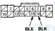
CONNECTOR D(16P)
CONNECTOR Q (20P)
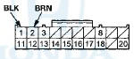
CONNECTOR R (24P)
*: 4-door
3. Inspect the connector and socket terminals to be sure they are all making good contact.
• If the terminals are bent, loose or corroded, repair them as necessary and recheck the system.
• If the terminals look OK, go to step 4 .
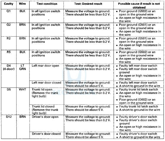
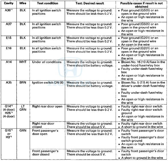
4. Reconnect the connectors to the driver's under-dash fuse/relay box, and do these input tests at the following connector.
• If any test indicates a problem, find and correct the cause, then recheck the system.
• If all the input tests prove OK go to step 5.
Passenger's MICU
5. Turn the ignition switch to LOCK (0), and remove the passenger's kick panel.
• 2-door (see page 20-105) • 4-door (see page 20-107) 6. Disconnect passenger's under-dash fuse/relay box connectors A, E, and G # 1 (or H*2).
*1: LX, LX PZEV, LX-P, LX-P PZEV
*2: Except LX, LX PZEV, LX-P, LX-P PZEV
NOTE: All connector views are wire side of female terminals.
CONNECTOR A (38P)
CONNECTOR G (16P) (LX, LX PZEV, LX-P, LX-P PZEV)
CONNECTOR H (38P) (Except LX, LX PZEV, LX-P, LX-P PZEV)
CONNECTOR E (18P)
*1: 4-door
*2: '08-09 models
7. Inspect the connector and socket terminals to be sure they are all making good contact.
• If the terminals are bent, loose or corroded, repair them as necessary and recheck the system.
• If the terminals look OK, go to step 8.
8. Reconnect the connectors to the passenger's under-dash fuse/relay box, and do these input tests at the following connectors.
• If any test indicates a problem, find and correct the cause, then recheck the system.
• If all the input tests prove OK, go to step 9.
*1:'08-09 models
*2: LX, LX PZEV, LX-P, LX-P PZEV
*3: Except LX, LX PZEV, LX-P, LX-P PZEV
9. If multiple failures are found on more than one control unit, replace the driver's under-dash fuse/relay box (includes the driver's MICU).
• USA models (see page 22-86) • Canada models (see page 22-87) If input failures are related to a particular control unit, replace the control unit
 Circuit Diagram
...
 Reminder Systems
...
See also:
Secondary Shaft Bearing
Replacement
Special Tools Required
•Driver Handle, 15 x 135L 07749-0010000
•Attachment, 62 x 68 mm 07746-0010500
1. Remove the set plate bolt, then remove the lock
washer (A) and the bearing set pla ...
Modifications
Do not modify your vehicle or use non-Honda components that can affect its
handling, stability, and reliability.
Overall vehicle performance can be affected. Always make sure all equipment
is
p ...
Front Seat Manual Adjustments
See pages for important safety
information and warnings about how to
properly position the seats and seatbacks.
Make all seat adjustments before
you start driving.
To adjust the seat forward ...