 Honda Accord: MICU Input Test
NOTE: • Before testing, troubleshoot the multiplex integrated control unit first, using B-CAN System Diagnosis Test Mode A (see page 22-134).
• Before testing, make sure the No. 5 (7.5 A) fuse in the driver's under-dash fuse/relay box is OK.
Driver's MSCU
1. Turn the ignition switch to LOCK (0), and remove the driver's dashboard lower cover (see page 20-166).
2. Disconnect driver's under-dash fuse/relay box connectors D, F, N, P, Q, and R.
NOTE: All connector views are wire side of female terminals.
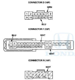
3. Inspect the connector and socket terminals to be sure they are all making good contact.
• If the terminals are bent, loose or corroded, repair them as necessary and recheck the system.
• If the terminals look OK, go to step 4 .
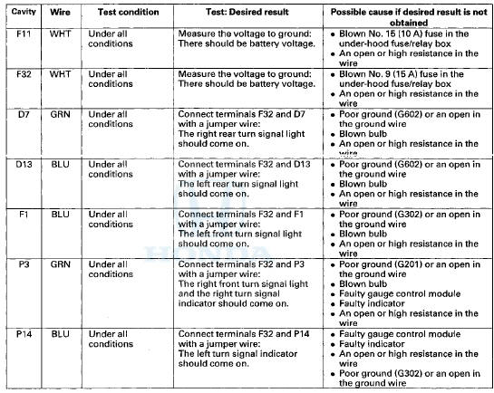
4. With the connectors still disconnected, do these input tests at the appropriate following connector.
• If any test indicates a problem, find and correct the cause, then recheck the system, • If all the input tests prove OK, go to step 5.
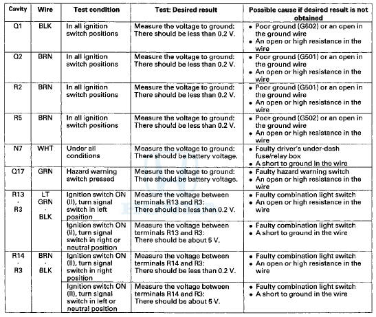
5. Reconnect the connectors to the driver's under-dash fuse/relay box, and make these input tests at the connectors.
• If any test indicates a problem, find and correct the cause, then recheck the system.
• If all the input tests prove OK, the driver's MICU must be faulty; replace the driver's under-dash fuse/relay box: - USA models (see page 22-86) - Canada models (see page 22-87)
 DTC Troubleshooting
DTC B1280: Turn Signal Switch Circuit
Malfunction
NOTE: If you are troubleshooting multiple DTCs, be sure
to follow the instructions in B-CAN System Diagnosis
Test Mode A (see page 22-134).
1. ...
 Hazard Warning Switch
Test/Replacement
Hazard Warning Switch
Test/Replacement
1. Remove these items:
• Center vent for w i t h navigation system (see page
20-178)
• Audio unit for without navigation system (see page
23-115)
2. Remove the hazard warning switch (A) ...
See also:
Audio Disc Changer
Removal/Installation
With Navigation
NOTE:
• Put on gloves to protect your hands.
• Take care not to scratch the dashboard and related
parts.
• Lay a shop towel under the parts when working on
the ...
DTC Troubleshooting
DTC 81152: Gauge Control Module (EEPROM)
Error
NOTE: If you are troubleshooting multiple DTCs, be sure
to follow the instructions in B-CAN System Diagnosis
Test Mode A (see page 22-134).
1. Cle ...
Recommended Engine Oil
Oil is a major contributor to your
engine’s performance and longevity.
Always use a premium-grade 0W-20
detergent oil displaying the API
Certification Seal. This seal indicates
the oil is e ...