 Honda Accord: End Cover Removal
Special Tools Required
Mainshaft Holder 07GAB-PF50101
1. Remove the three bolts (D) securing the ATF cooler inlet line brackets, the ATF filter bracket bolts (E), the ATF cooler line banjo bolts (F), and remove the ATF cooler line/ATF filter (G) and the filter brackets (H).
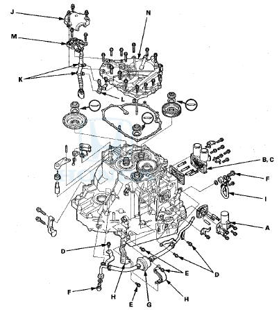
2. Remove the ATF cooler outlet line (I).
3. Remove A/T clutch pressure control solenoid valve A, the ATF joint pipes, the O-rings, the ATF pipe, and the gasket.
4. Remove A/T clutch pressure control solenoid valves B and C with the harness brackets, the ATF joint pipes, the O-rings, and the gasket.
5. Remove the transmission range switch cover (J).
6. Remove the transmission range switch harness clamps (K) from the clamp bracket (L), then remove the transmission range switch (M).
7. Remove the end cover (N), the dowel pins, the O-rings, and the end cover gasket.
8. Install the mainshaft holder onto the mainshaft.
9. Engage the park pawl with the park gear.
10. Cut the lock tab (A) of the each shaft locknut (B) using a chisel (C). Then remove the locknuts and the conical spring washers from each shaft.
NOTE:
-Countershaft and secondary shaft locknuts have left-hand threads.
-Keep all of the chiseled particles out of the transmission.
-Clean the old mainshaft and the old countershaft locknuts; they are used to install the press fit idler gear on the mainshaft, and the park gear on the countershaft.
11. Remove the mainshaft holder from the mainshaft.
12. Set a two-jaw (or three-jaw) puller (A) on the countershaft (B) with a spacer (C) between the puller and the countershaft, then remove the park gear (D).
13. Install a puller (A) with two 6 x 1.0 mm bolts (B) on the mainshaft idler gear (C). Set a spacer (D) between the puller and the mainshaft (E), then remove the mainshaft idler gear.
14. Remove the park pawl (F), the park pawl spring (G), the park pawl shaft (H), and the stop shaft (I).
15. Remove the park lever (J) from the selector control shaft (K).

 Park Lever Stop Inspection and
Adjustment
Park Lever Stop Inspection and
Adjustment
1. Set the park lever in the P position.
2. Measure the distance (A) between the park pawl shaft
(B) and the park lever roller pin (C).
Standard: 57.7-58.7 mm (2.27-2.31 in)
3. If the measurem ...
See also:
Checking Wiper Blades
If the wiper blade rubber has deteriorated, it will leave streaks and the
metal wiper
arm may scratch the window glass. ...
Clutch Wave-plate Phase Difference
Inspection
1. Place the clutch wave-plate (A) on a surface plate, and
set a dial indicator (B) on the wave-plate.
2. Find the bottom (C) of a phase difference of the
wave-plate, zero the dial indicator an ...
Parking Your Vehicle
Do not park your vehicle near flammable objects,
such as dry grass, oil, or timber.
Heat from the exhaust can cause a fire.
When Stopped
1. Depress the brake pedal firmly.
2. Firmly apply the p ...