 Honda Accord: Electrical Compass Zone Selection
and Calibration
Honda Accord: Electrical Compass Zone Selection
and Calibration
NOTE: • You should do this procedure any time the electrical compass unit is replaced.
• You should do this procedure in an open area away from buildings, power lines, and other vehicles.
• If you see "  " and the CAL
indicator is shown in the
audio-HVAC display, the electrical compass unit is
self-calibrating.
• The electrical compass unit may need to be manually calibrated after exposure to a strong magnetic field. If the electrical compass unit seems to be continually showing the wrong direction, and is not self-calibrating, do the following.
1. Check the No. 15 (10 A) fuse in the under-hood fuse/ relay box and the No. 5 (7.5 A) and the No. 18 (7.5 A) fuses in the driver's under-dash fuse/relay box.
2. Turn the ignition switch to ON (II), then press and hold the MENU button (A) until it beeps (about 2 seconds).
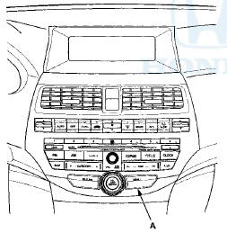
3. Turn the selector knob (A) to select ZONE.
4. Press t h e s e l e c t o r knob (A) t o enter y o u r selection.
The d i s p l a y s h o w s t h e c u r r e n t l y selected zone number.
NOTE: If necessary, press t h e RETURN b u t t o n (B) t o return t o t h e p r e v i o u s d i s p l a y . Pressing t h e MENU b u t t o n (C) cancels t h e electrical compass s e t t i ng mode.
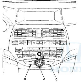
5. F i nd t h e zone f o r y o u r area o n t h e m a p . If t h e correct zone is n o t s h o w n , t u r n t h e selector knob to cycle t he zone list u p o r d o w n .
6. Once t h e correct zone is displayed, press t h e selector knob. The display t h e n returns t o n o r m a l .
7. T u r n t h e selector k n o b t o select CALIBRATION.
8. Press the selector knob to enter your selection. The display shows PUSH CAL START.
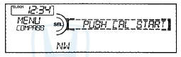
9. Press the selector knob, the compass display will blink and the CAL indicator is shown.
10. When the calibration is successfully completed, the CAL indicator goes off and the compass display will stop blinking and show an actual heading.
NOTE: • While setting, pressing the RETURN button returns to the previous display. Pressing the MENU button (A) cancels the compass setting mode.
• The audio system is not related to the compass system. Even if the compass system is calibrating, the display returns to the normal display which you selected last.
• Do this procedure in an open area, away from buildings, power lines, and other vehicles.
 Circuit Diagram
...
 Electrical Compass Unit Input
Test
Electrical Compass Unit Input
Test
1. Remove the rear shelf (see page 20-128).
2. Loosen the bolts (A), then pull out the electrical compass unit bracket (B).
3. Disconnect the 6P connector (C) and remove the mounting bolt ( D ) ...
See also:
License Plate Light Replacement
4-door
1. Poll the license plate light assembly out, and
disconnect the 2P connector (A) from the license plate
light.
License Plate Light: 5W
2. Separate the lens (B) and housing (C), then rem ...
CMP Sensor A Replacement
1. Disconnect the CMP sensor A 3P connector (B).
2. Remove CMP sensor A from the intake camshaft side
of the cylinder head.
3. Install the parts in the reverse order of removal with a
new O-ri ...
Battery Removal and Installation
NOTE: The battery terminal disconnection and
reconnection procedure (see page 22-91) must be done
before and after doing this procedure- Some systems
store data in memory that is lost when the batt ...