 Honda Accord: Driveshaft Removal
Special Tools Required
-Ball Joint Thread Protector, 14 mm 07AAE-SJAA100
-Ball Joint Remover, 28 mm 07MAC-SL0A202
1. Raise and support the vehicle, (see page 1-13) 2. Remove the front wheels.
3. Pry up the stake (A) on the spindle nut (B), then remove the nut.
4. Drain the transmission fluid, then reinstall the drain plug with a new sealing washer: -Manual transmission (see page 13-5) -Automatic transmission (see page 14-192) 5. Hold the stabilizer link joint pin (A) using a hex wrench (B), and remove the flange nut (C). Separate the front stabilizer link (D) from the lower arm.
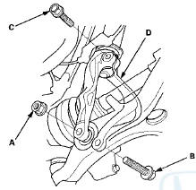
6. Remove the damper fork mounting nut (A), the damper fork mounting bolt (B), and the damper pinch bolt (CL then remove the damper fork (D).
7, Remove the cotter pin (A) from the knuckle ball joint, then remove the castle nut (B). Separate the ball joint from the lower arm (C) using the 28 mm ball joint remover and the 14 mm ball joint thread protector (see page 18-10).
NOTE: -Be careful not to damage the ball joint boot when installing the remover.
-Do not force or hammer on the lower arm, or pry between the lower arm and the knuckle. You could damage the ball joint.
8. Pull the knuckle outward, and separate the outboard joint from the front hub using a plastic hammer.
9. Left driveshaft: Pry the inboard joint (A) from the differential using a prybar. Remove the driveshaft (B) as an assembly.
NOTE: -Do not pull on the driveshaft, or the inboard joint may come apart. Pull the inboard joint straight out to avoid damaging the oil seal.
-Be careful not to damage the oil seal or the end of the inboard joint using the prybar.
10. Right driveshaft: Drive the inboard joint (A) off of the intermediate shaft using a drift punch and a hammer.
Remove the driveshaft (B) as an assembly.
NOTE: Do not pull on the driveshaft, or the inboard joint may come apart.
11. Remove the set ring (A) from the left driveshaft inboard joint.

12. Remove the set ring (A) from the intermediate shaft.
 Driveshaft Inspection
1. Check the inboard boot (A) and the outboard boot (B)
on the driveshaft (C) for cracks, damage, leaking
grease, and loose boot bands (D). If any damage is
found, replace the boot and the boot ban ...
 Driveshaft Disassembly
Special'Tools Required
•Threaded Adapter, 26 x 1.5 mm
07XAC-001030A
-Slide Hammer 5/8M-18 UNF, commercially available
-Bearing Puller, commercially available
-Boot Band Pliers, commercially ...
See also:
Tire Pressure Monitoring System (TPMS) - Required Federal Explanation
Each tire, including the spare (if
provided), should be checked
monthly when cold and inflated to
the inflation pressure recommended
by the vehicle manufacturer on the
vehicle placard or tir ...
Suspension
...
Forward Collision Warning (FCW)*
Alerts you when it detects the possibility of your vehicle colliding with the
vehicle in
front of yours.
If the system determines a collision is possible, it gives both visual and
audible alert ...