 Honda Accord: Countershaft Reverse Selector Hub and
3rd Gear Removal
Honda Accord: Countershaft Reverse Selector Hub and
3rd Gear Removal
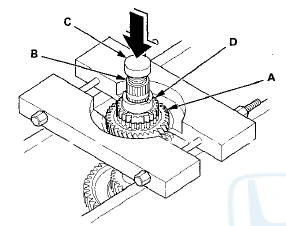
1. Install a commercially available bearing separator on 4th gear (A). Set the countershaft (B) on a press with a spacer (C) between the press and the countershaft, and remove the reverse selector hub (D).
NOTE: Some reverse selector hubs are not press-fitted, and can be removed without using the bearing separator and a press.
2. Remove the needle bearing, the set ring, the 35 x 47 x 7.8 mm collar, and the 31 mm cotters.
3. Set the countershaft (A) on the press with the spacer (B) between the press and the countershaft, and remove 3rd gear (C).
4. Remove the 37 x 41 x 54.3 mm collar, 5th gear, 1st gear, and 2nd gear.
 Countershaft Disassembly, Inspection,
and Reassembly
Countershaft Disassembly, Inspection,
and Reassembly
1. Inspect the needle bearings for galling and rough movement.
2. Inspect the splines for excessive wear and damage.
3. Check the shaft bearing surface for scoring and excessive wear.
4. Lubr ...
 Countershaft Reverse Selector Hub and
3rd Gear Installation
Countershaft Reverse Selector Hub and
3rd Gear Installation
Special Tools Required
Driver Handle, 40 mm I.D. 07746-0030100
1. Install 2nd gear, 1st gear, 5th gear, and the
37 x 41 x 54.3 mm collar on the countershaft.
2. Slide 3rd gear (A) over the count ...
See also:
DTC Troubleshooting
DTC B10CF: Left Daytime Running Lights
Circuit Malfunction
NOTE:
• Make sure the No. 15 (7.5 A) fuse in the driver's
under-dash fuse/relay box is OK.
• If you are troubleshooting mult ...
Rear Seat-back Cover Replacement
2-door
NOTE:
- Put on gloves to protect your hands.
- Take care not to tear or damage the seat covers.
1. Remove the seat-back (see page 20-239).
2. Remove all of the head restraints.
3. ...
Emissions Testing
Testing of Readiness Codes
If you take your vehicle for an
emissions test shortly after the
battery has been disconnected or
gone dead, it may not pass the test.
This is because of certain ‘ ...