
 Honda Accord: Console Accessory Power Socket
Test/Replacement
Honda Accord: Console Accessory Power Socket
Test/Replacement
NOTE: If all of the front and console accessory power sockets do not work, check the No. 1 8 (7.5 A) fuse in the driver's under-dash fuse/relay box and ground (G503) first.
1. Remove the center console panel (see page 20-157).
2. Disconnect the 2P connector (A) f r om the console accessory power socket (B).
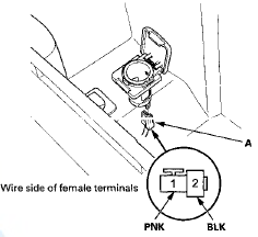
3. Inspect the connector terminals to be sure they are all making good contact.
• If the terminals are bent, loose, or corroded, repair them as necessary and recheck the system.
• If the terminals look OK, go to step 4.
4. Turn the ignition switch to ACCESSORY (I).
5. Measure the voltage between console accessory power socket relay terminal No. 3 and body ground.
There should be less than 0 . 2 V.
• If there is less than 0.2 V, go to step 6.
• If there is more than 0.2 V, check for: - An open or high resistance in the wire between console accessory power socket relay terminal No. 3 and body ground (G503).
- Poor ground (G503).
6. Measure the voltage between console accessory power socket 2P connector terminal No. 1 and body ground. There should be battery voltage.
• If there is battery voltage, go to step 7.
• If there is no voltage, check for:
- A blown No. 12 (20 A) fuse in the passenger's under-dash fuse/relay box
- A faulty console accessory power socket relay
- An open or high resistance in the wire between console accessory power socket relay terminal No. 1 and console accessory power socket 2P connector terminal No. 1.
7. Check for continuity between the console accessory power socket terminal No. 2 and body ground. There should be continuity.
• If there is continuity, replace the power socket; go to step 8.
• If there is no continuity, check for:
- Poor ground (G503).
- An open or high resistance in the wire between console accessory power socket 2P connector terminal No. 2 and body ground (G503).
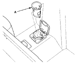
8. Remove the socket (A).
9. Remove the housing (A) from the panel.
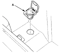
10. Install the power socket in the reverse order of removal.
 Front Accessory Power Socket
Test/Replacement
Front Accessory Power Socket
Test/Replacement
NOTE: If all of the front and console accessory power
sockets do not work, check the No. 18 (7.5: A> fuse in the
driver's under-dash fuse/relay box and ground (G503)
first.
1. Remove the cent ...
 Power Mirrors
...
See also:
General Information
Before programming your
HomeLink to operate a garage door
opener, confirm that the opener has
an external entrapment protection
system, such as an ‘‘electronic eye,’’
or other safety ...
How Your Front Airbags Work
If you ever have a moderate to
severe frontal collision, sensors will
detect the vehicle’s rapid
deceleration.
If the rate of deceleration is high
enough, the control unit will inflate
...