 Honda Accord: Clutch Replacement
Special Tools Required
- Clutch Alignment Disc 07JAF-PM7011A
- Ring Gear Holder 07LAB-PV00100 or 07924-PD20003
- Clutch Alignment Tool Set 07PAF-0020000
- Clutch Alignment Pilot, 21 mm 07PAF-0020370
- Clutch Alignment Shaft 07ZAF-PR8A100
- Attachment 22 x 24 mm 07746-0010800
- Driver Handle, 15 x 135L 07749-0010000
- Remover Handle 07936-3710100
- Bearing Remover Shaft S e t 20 mm 07936-3710600
- Slide Hammer 07936-371020A
Engine Side
Pressure Plate Inspection and Removal
1. Remove the transmission (see page 13-7).
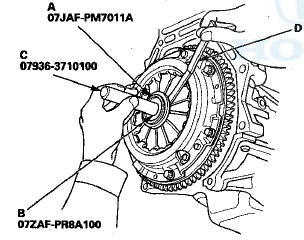
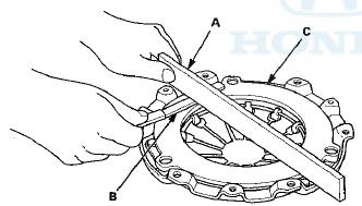
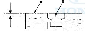
2. Check the evenness of the height of the diaphragm spring fingers using the clutch alignment disc (A), the clutch alignment shaft (B), the remover handle (C), and a feeler gauge (D). If the height difference is more than the service limit, replace the pressure plate.
Standard (New): 0.6 mm (0.02 in) max.
Service Limit: 0.8 mm (0.03 in)
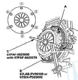
3. Install the ring gear holder (A), the clutch alignment tool set (B), and the 21 mm clutch alignment pilot (C).
4. To prevent warping, loosen the pressure plate mounting bolts (D) in a crisscross pattern in several steps, then remove the pressure plate (E).
5. Inspect the fingers of the diaphragm spring (A) for wear at the release bearing contact area.
6. Inspect the pressure plate surface (A) for wear, cracks, and burning.
7. Measure across the pressure plate (C), If the most measurement difference is more than the service limit, replace the pressure plate.
Standard (New): 0.03 mm (0401; in) max.
Service Limit: 0.15 mm (0.006 in)
Clutch Disc Inspection and Removal
8. Remove the clutch disc (A), the clutch alignment tool set (B), and the 21 mm clutch alignment pilot (C).
9. Inspect the lining of the clutch disc for signs of slippage or oil. If the clutch disc looks burnt or is-oil soaked, replace the clutch disc. If the clutch disc is oil soaked, find and repair the source of the oil leak. .
10. Measure the clutch disc thickness. If the measurement is less than the service limit, replace the clutch disc.
Standard (New): 7.30-7.90 mm (0.287-0.311 in) Service Limit: '6.0 mm (0.24 in)
11. Measure the depths of the rivets from the clutch disc lining surface (A) to the rivets (B) on both sides. If the measurement is less than the service limit, replace the clutch disc.
Standard (New): 1.15-”1.75 mm
(0.045-0.069 in)
Service Limit: 0.7 mm (0.03 in)
Flywheel Inspection
12. Remove the ring gear holder.
13. Inspect the ring gear teeth for wear and damage.
14. Inspect the clutch disc mating surface on the flywheel for wear, cracks, and burning.
15. Measure the flywheel (A) runout using a dial indicator (B). Through at least two full turns with pushing against the flywheel each time you turn it to take up the crankshaft thrust washer clearance. If the measurement is not within the standard, replace the flywheel, and recheck the runout; then go to step 16.
Standard (New): 0.05 mm (0.002 in) max.
Service Limit: 0.15 mm (0.006 in)
Flywheel Replacement
16. Install the ring gear holder (A).
17. Loosen the flywheel mounting bolts in a crisscross pattern in several steps. Remove the bolts, then remove the flywheel and the ring gear holder.
18. Install the flywheel on the crankshaft, and install the mounting bolts finger-tight.
19. Install the ring gear holder (A), then torque the flywheel mounting bolts (B) in a crisscross pattern in several steps.
Crankshaft Pilot Bushing Inspection
20. Inspect the crankshaft pilot bushing for wear and damage.
21. Inspect the inside surface of the crankshaft pilot bushing with your finger. If the crankshaft pilot bushing is not smooth, replace it; then go to step 22.
Crankshaft Pilot Bushing Replacement
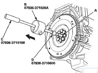
22. Remove the crankshaft pilot bushing (A) using the slide hammer (B), the remover handle (C), and the 20 mm bearing remover shaft set (D).
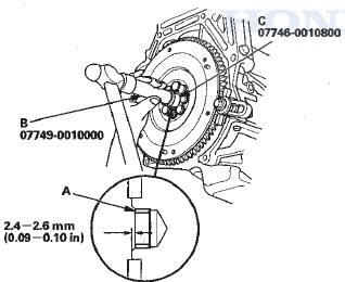
23. Install a new crankshaft pilot bushing (A) into the crankshaft using the 15 x 135L driver handle (B) and the 22 x 24 mm attachment (C).
Clutch Disc and Pressure Plate Installation
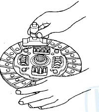
24. Temporarily install the clutch disc onto the splines of the transmission mainshaft. Make sure the clutch disc slides freely on the mainshaft.
25. Apply a light coat of super high temp urea grease (P/N 08798-9002) to the crankshaft pilot bushing (A).
26. Apply super high temp urea grease (P/N 08798-9002) to the splines (B) of the clutch disc (C), then install the clutch disc using the clutch alignment tool set (D), and the 21 mm clutch alignment pilot (E).
27. Install the pressure plate (A) and the mounting bolts (B) finger-tight.
28. Torque the mounting bolts (A) in a crisscross pattern.
Tighten the bolts in several steps to prevent warping the diaphragm spring.
Specified Torque: 25 N-m (2.6 kgfm, 19 Ibf-ft)
29. Remove the ring gear holder (B), the clutch alignment tool set (C), and the 21 mm clutch alignment pilot.
30. Make sure the diaphragm spring fingers are all the same height.
31. Do the release bearing inspection, and replace it if necessary.
32. Install the transmission (see page 13-15).
Transmission Side
Release Bearing Removal
1. Remove the transmission (see page 13-7).
2. Remove the release fork boot (A) from the clutch housing (B).
3. Remove the release fork (C) from the clutch housing by squeezing the release fork set spring (D) with pliers. Remove the release bearing (E).
Release Bearing Inspection
4. Check the play of the release bearing by spinning it by hand. If there is excessive play or noise, replace the release bearing.
NOTE: The release bearing is packed with grease. Do not wash it in solvent.
Release Bearing Installation
5. Apply super high temp urea grease (P/N 08798-9002) to the release fork (A), the release fork bolt (B), the release bearing (C), and the release bearing guide (D) in the shaded areas, then set the release fork set spring (E).
NOTE: Replace the release fork bolt if necessary.
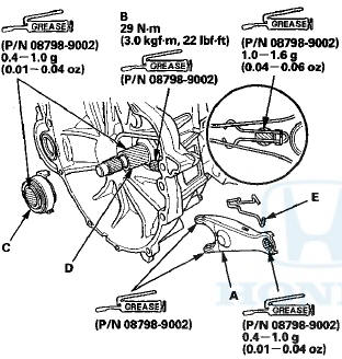
6. With the release fork (A) slid between the release bearing pawls (B), install the release bearing on the mainshaft while inserting the release fork through the hole (C) in the clutch housing.

7. Align the detent (D) of the release fork with the release fork bolt (E), then press the detent of the release fork over the release fork bolt squarely.
8. Install the release fork boot (F). Make sure the boot seals around the release fork and the clutch housing.
9. Move the release fork (A) right and left to make sure that it fits properly against the release bearing (B) and that the release bearing slides smoothly. Wipe off any excess grease.
10. Install the transmission (see page 13-15).
 Clutch Hose Replacement
NOTE:
- Replace the clutch hose if it is twisted, cracked, or
leaks.
- Use fender covers to avoid damaging painted
surfaces.
- Do not spill brake fluid on the vehicle; it may damage
the pain ...

See also:
Playing Discs (Models with navigation system)
Playing Discs (Models with navigation system)
Your vehicle’s audio system has an
in-dash disc changer with the same
controls used for the radio. To
operate the disc changer, the ignition
...
System Description
Security Alarm
The security alarm system is armed automatically after
the doors, hood, and trunk lid are closed and locked. For
the system to arm, the ignition switch must be in the
LOCK (0) posit ...