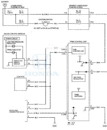
 Honda Accord: Circuit Diagram
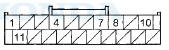
DRIVER'S UNDER-DASH FUSE/RELAY BOX CONNECTOR N (16P)
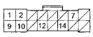
Wire side of female terminals
DRIVER'S UNDER-DASH FUSE/RELAY BOX CONNECTOR P (20P)
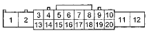
Wire side of female terminals
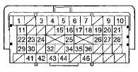
GAUGE CONTROL MODULE 32P CONNECTOR
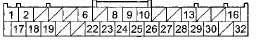
Wire side of female terminals
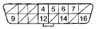
TPMS CONTROL UNIT 20P CONNECTOR
Wire side of female terminals
ECM/PCM CONNECTOR A (49P)
Terminal side of female terminals
DATA LINK CONNECTOR (DLC)
Terminal side of female terminals
 System Description
TPMS Control Unit Inputs and Outputs for 20P Connector
Wire side of female terminals
System Structure
Once the vehicle speed exceeds 28 mph (45 km/h), the TPMS control unit
monitors all four ...
 DTC Troubleshooting
DTC 11,13,15,17: Tire Low Air Pressure
NOTE: If low tire pressure is detected, the TPMS control
unit sets one or more of these DTCs, and turns on the
low tire pressure indicator. If the low tire pr ...
See also:
Emblem/Sticker Replacement
2-door
NOTE: When removing emblems/sticker, take care not to scratch the body.
1. To remove the front "H" emblem, remove the front bumper (see page 20-255).
2. Clean the body surfaces ...
Replacing a Fog Light Bulb
If equipped
Your vehicle uses halogen light
bulbs. When replacing a bulb, handle
it by its plastic case, and protect the
glass from contact with your skin or
hard objects. If you touch the gl ...