
 Honda Accord: Brake System Bleeding
NOTE: - Do not reuse the drained fluid. Use only new Honda DOT 3 Brake Fluid from an unopened container. Using a non-Honda brake fluid can cause corrosion and shorten the life of the system.
- Make sure no dirt or other foreign matter gets in the brake fluid.
- Do not spill brake fluid on the vehicle; it may damage the paint. If brake fluid does contact the paint, wash it off immediately with water.
- The reservoir connected to the master cylinder must be at the MAX (upper) level mark at the start of the bleeding procedure and checked after bleeding each wheel location. Add fluid as required.
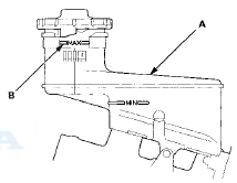
1. Make sure the brake fluid level in the reservoir (A) is at the MAX (upper) level line (B).
2. Have someone slowly pump the brake pedal several times, then apply steady pressure.
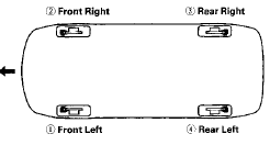
3. Start the bleeding at the driver's side of the front brake system.
NOTE: Bleed the calipers in the sequence shown.
BLEEDING SEQUENCE
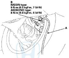
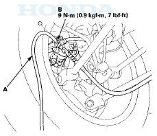
4. Attach a length of clear drain tube (A) to the bleed screw (B), then loosen the bleed screw to allow air to escape from the system. Then tighten the bleed screw securely.
NOTE: The illustrations show the NISSIN type.
Front
Rear
5. Refill the master cylinder reservoir to the MAX (upper) level line.
6. Repeat the procedure for each brake circuit until there are no air bubbles in the fluid.
 Parking Brake Inspection and Adjustment
Inspection
1. Pull the parking brake lever (A) with 196 N
(20 kgf, 44 Ibf) of force to fully apply the parking brake.
The parking brake lever should be locked within the
specified number of clic ...

See also:
Trunk Light Test/Replacement
1. Open the trunk lid.
2. Carefully pry out the trunk light (A).
Trunk Light: 5 W
3. Disconnect the 2P connector (B) from the trunk light.
4. Check for continuity between terminals No. 1 ( + ...
Cruise Control Combination
Switch Test/Replacement
SRS components are located in this area. Review the
SRS component locations:
2-door fsee page 24-23)
4-door (see page 24-21)
Precautions and procedures (see page 24-25), in the SRS
before d ...
Idler Gear/Idler Gear Shaft
Replacement
Special Tools Required
-Driver Handle, 15 x 135L 07749-0010000
-Attachment, 32 x 35 mm 07746-0010100
1. Remove the snap ring from the idler gear/idler shaft
assembly. Do not distort the snap ring. ...